115
TRAK Machine Tools
Southwestern Industries, Inc.
ProtoTRAK SMX, K2, K3 & K4 & Retrofit Safety, Installation, Maintenance, Service and Parts List Manual
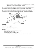
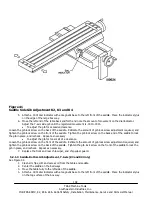
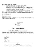
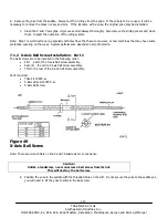
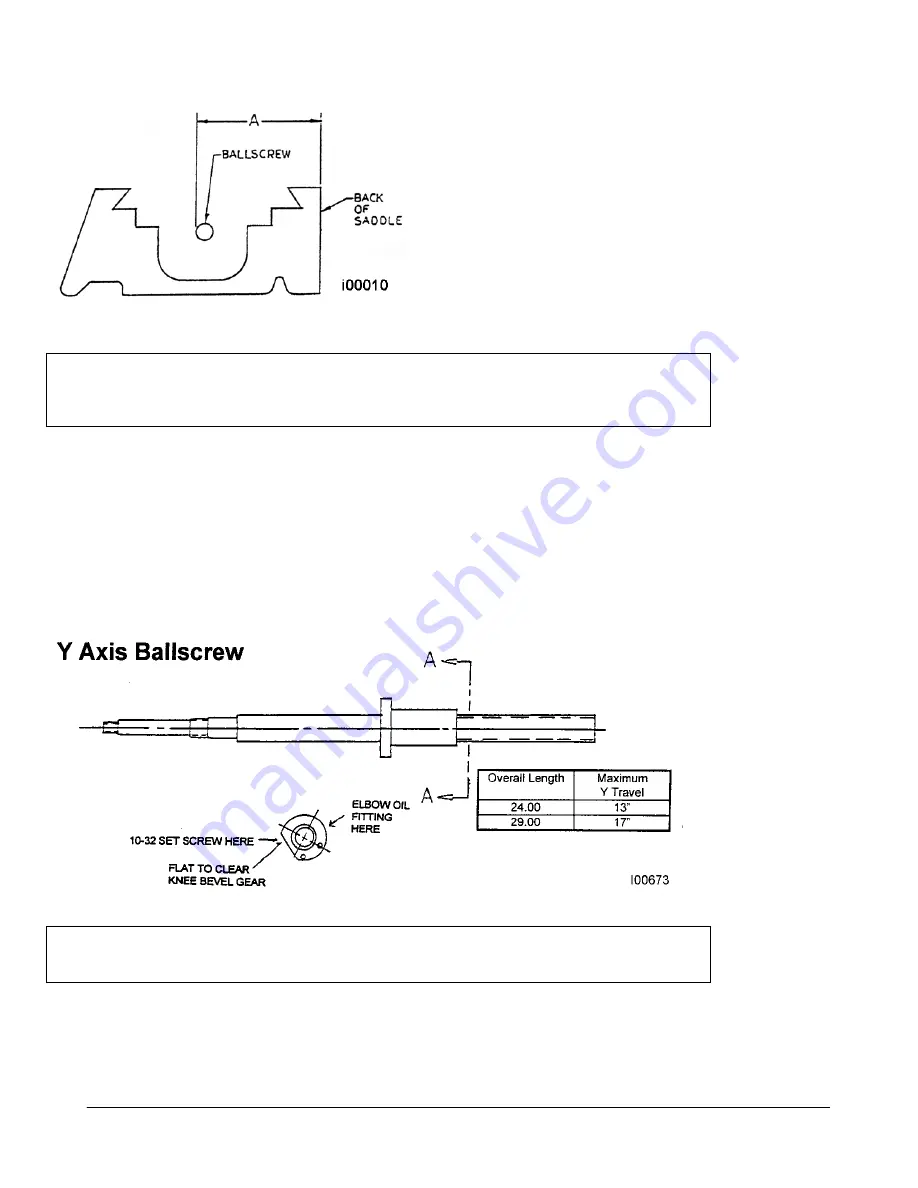
Take measurement “A” on the left and right sides of the saddle
casting. So that the measurements are comparable, measure
from the OD of the thread of the ballscrew on both sides.
Note: If the back of the saddle casting is not a suitable reference,
it may be necessary to position a piece of round stock inside the
back dovetail to be used as a reference point.
Adjust the position of the yoke until the two measurements are within 0.005” end to end (maximum).
Caution!
The alignment of the ballscrew is crucial.
Misalignment can cause damage to the ballscrews and drive assemblies
as well as poor system performance.
16. Tighten the yoke to the saddle casting. Check the alignment again to be sure
the yoke did not move as it was tightened. Pin the yoke in position using the
provided roll pin.
7.1.3 Y-Axis Ball Screw Installation
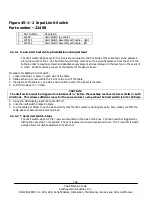
Parts required
Yoke kit (already opened)
Y-Axis drive assembly 23083-xx
Y-Axis ball screw
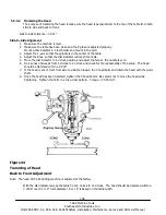
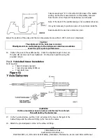
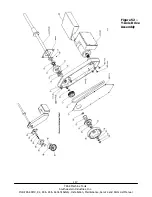
Figure 51
CAUTION!
Unlike a leadscrew never unscrew a ball screw from its nut.
This will destroy the ball screw.
17. In the Y-axis ball screw, put the 10-32 set screw in the hole on flat part of the
ballnut flange and the elbow oil fitting in the hole on the radius.
18. Attach the provided plastic oil line to the elbow oil fitting.

