134
TRAK Machine Tools
Southwestern Industries, Inc.
ProtoTRAK SMX, K2, K3 & K4 & Retrofit Safety, Installation, Maintenance, Service and Parts List Manual
Caution!
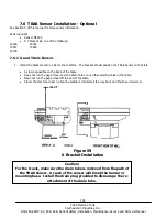
After the readerhead is attached to the readerhead mounting bracket, do not
move the machine axis until the shipping brackets are removed. This will
break the readerhead.
Caution!
Do not pinch the wires.
3.
Mount the scale to the table:
Transfer the center hole first to use as a pivot point.
Align the scale so that it is within 0.005” end to end.
Transfer the holes on the ends and install the screws.
Re-check the alignment.
4.
From the readerhead on the scale, remove the nameplate, shield and wires so that the mounting holes are
accessible.
5.
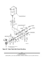
Attach the readerhead to the readerhead mounting bracket:
There are jackscrews on the readerhead to compensate for some gap between the readerhead and the
readerhead mounting bracket.
Before tightening the readerhead to the bracket, there must be a .002 - .003” gap between the readerhead
mounting bracket and the jackscrews. Tightening the mounting screws will eliminate this gap.
6.
Replace the wires, shield and nameplate.
7. Remove the shipping brackets that fix the readerhead to the scale for shipping.
7.7.2 Y Axis Scale Installation
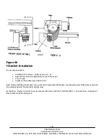
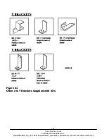
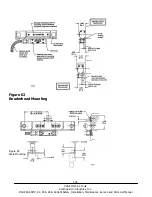
1. Install the readerhead mounting bracket to the side of the saddle.
Note: Once the readerhead mounting bracket is installed, position the scale and mounting spar assembly in position in
order to determine the amount of spacers needed for the mounting spar. Also ensure that the scale is long enough for
the saddle travel.
2. Transfer the mounting spar holes to the saddle and mount it.
Note: the mounting spar must be parallel to the Y-axis travel within .005” end to end both horizontally and vertically.
Use spacers and shims as necessary.
3. Slide the scale into the mounting spar and fasten.
Note: the rest of the installation is the same as for the X-axis, Steps 5 through 7.


