5
GB
by the load and the weight of the hoist. Whoever installs
the machine must check that the structure on which
the hoist is mounted is suitable to withstand the stress
indicated below.
WINDOW OR CEILING SUPPORT
See App C – Hoist structure (Options)
Window or ceiling strut support
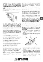
In addition to the limiting reactions described in the
figure, the hoist under a load condition generates a
tilting moment Mr that must be balanced by placing the
screw under tension, checking the support capacity of
the floor, ceiling and/or wall structure.
The forces Ffʺ and Fsʺ reported in the table, refer to the
worst possible load conditions (minimum strut length).
Based on the dimensions and type of load to be lifted,
the device must be installed so that the load does not
strike against other moving bodies or against stationary
parts of the adjacent structures during the lifting and
lowering movement.
The user must take all the necessary
precautions, regardless of the type of installation
created, to protect himself against the risk of
falling. In particular, the user must strictly comply
with the following instructions:
a) The scaffolding of the mountings must be sufficiently
wide and, on the sides towards the empty space,
equipped with a normal guard and toe board.
b) An opening may be left to pass a shovel or bucket
provided that a toe board with a height of no less than
30 cm is installed at that point. The opening must be
reduced to what is strictly necessary and delimited
by strong and rigid side supports, for which the one
opposite to the pulling position must be additionally
protected with fixed scaffolding elements.
c) Two iron brackets, projecting at least 20 cm, must be
applied on the inner side of the supports described
above, at a height of 1.20 m and perpendicular to the
opening, which will be used as a support and guard
for the worker.
d) The boards of the single shelves must be formed with
planks with a thickness of no less than 5 cm which
must rest on the cross members and have a section
and centre distance that are sized in relation to the
maximum load foreseen for each of the shelves.
Summary of Contents for 261579
Page 47: ...47 Schemi elettrici Electrical diagrams Schémas électriques Schaltpläne Esquema alambricos E ...
Page 48: ......
Page 49: ......
Page 50: ......
Page 51: ......


