7
GB
ATTENTION
:
In order to obtain the best results from
the elevator, be careful not to overheat the motor;
incorrect use could result in the breaking system
jamming and the winding of the motor burning out.
BRAKE ADJUSTMENT
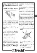
The self-braking motor consists of a induction motor
and a brake shoe.
Its unique characteristic lies in its ability to exploit
the motor flux and the brake shoe. This is due o the
particular way in which the motor has been constructed,
which allows the ferromagnetic insert to more towards
the brake shoe anchor, which in turn is attacted to the
rotor when the motor is connected. When the motor is
disconnected the rotor is blocked.
The braking force is regulated by adjusting the relevant
adjustment screw (V.R.) which also serves to unblock
the motor. To increase braking, turn the screw anti-
clockwise.
To decrease braking, turn the screw clockwise.
If the flange (sintered) shows wear, this is due to
the irregular performance of the brake. This can be
adjusted by regulating the rear ring nut (4) as follows:
1. Remove the fan cover (1) and the fan (2):
2. Loosen the three screws (3);
3. Make s ¼ anti-clockwise turn on the ring nut (4), if
the brake locks, make a ¼ clockwise turn;
4. Thoroughly tighten the three screws (3);
5. Replace the fan and the fan cover.
The load braking system must be checked every six
months and, in any case, each time that, during normal
machine use, the load does not stop immediately.
It is absolutely prohibited to disassemble or
access the internal parts of the hoist without first
cutting off the power supply by pulling the plug out
of the power outlet.
The operator must work in a safe position, i.e. so that
he is protected against falling and so that he has an
unobstructed view of the trajectory of the moving
elements.
If the operator uses safety belts to protect himself
against falling, they must be anchored to fixed parts and
absolutely immovable.
The hoist stand, the ceiling or window strut or
any other part of the machine support structure
cannot be used as an anchor point for safety belts.
Access to the area underneath the vertical axis of the
load must be prohibited to persons or at least a sign
must indicate the danger due to suspended loads.
Cordon off the working area under the elevator
and erect warning signs, as required by law. There
is always the risk of material falling accidentally or
breakage of the cable during working operations.
Do not walk or stand in the area under the elevator.
The user must still check that there are no persons in
the area underneath the vertical axis of the load.
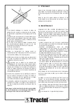
The loads must be lifted with a vertical pull
and therefore it is prohibited to use the hoist with
an oblique lift.
– It is recommended to sling the load perfectly and
to use adequate containers for liquid or sandy
substances.
– It is prohibited to use the lifting cable to sling the load
(see drawing).
– It is prohibited to grab or touch the lifting cable while
lifting or lowering the load, in particular near the lifting
limit switch.
– The machine is built with an IP44 motor meaning
that it is protected against solid bodies with sizes that
are greater than one millimeter and against water
infiltration in all directions.
– Therefore, it is prohibited to use the machine in
environments that are saturated with gas or if
exposed to direct streams of water or rain.
Summary of Contents for 261579
Page 47: ...47 Schemi elettrici Electrical diagrams Schémas électriques Schaltpläne Esquema alambricos E ...
Page 48: ......
Page 49: ......
Page 50: ......
Page 51: ......


