


ENGINE - 1NZ-FE ENGINE
D13N07
285EG76
Chamber A
Fresh Air Line
Refueling
Valve (Open)
Chamber B
From Fuel
Tank
Internal Pressure
Canister
During Refueling
To Fuel
Tank
Positive Pressure
(Fuel Tank Pressure)
Restrictor Passage
Negative Pressure
(Intake Manifold Pressure)
During Purge Operation or
System Monitoring Operation
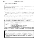
228TU119
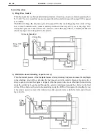
Fuel Tank Cap
Fresh Air
Fuel Inlet Pipe
To Canister
Cleaned Drain Air
EG-48
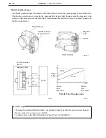
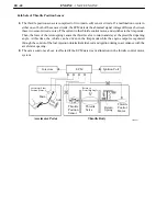
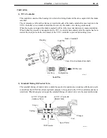
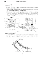
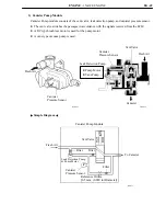
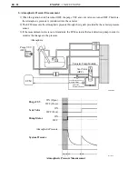
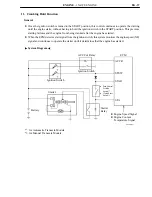
Construction and Operation
1) Refueling Valve
The refueling valve consists of chamber A, chamber B, and the restrictor passage. A constant
atmospheric pressure is applied to chamber A.
During refueling, the internal pressure of the fuel tank increases. This pressure causes the refueling
valve to lift up, allowing the fuel vapors to enter the canister.
The restrictor passage prevents the large amount of vacuum that is created during purge operation or
system monitoring operation from entering the fuel tank, and limits the flow of the vapor gas from the
fuel tank to the canister. If a large volume of vapor gas recirculates into the intake manifold, it will
affect the air-fuel ratio control of the engine. Therefore, the role of the restrictor passage is to help
prevent this from occurring.
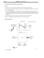
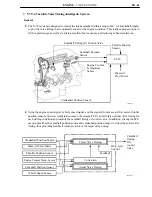
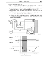
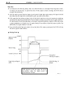
2) Fuel Inlet (Fresh Air Line)
In accordance with the change of structure of the evaporative emission control system, the location of
a fresh air line inlet has been changed from the air cleaner section to the near fuel inlet. The flesh air from
the atmosphere and drain air cleaned by the canister will go in and out of the system through the passage
shown below.
Summary of Contents for 1NZ-FE
Page 59: ...EG 60 MEMO ...


