G9000 Installation and Operation Manual
45
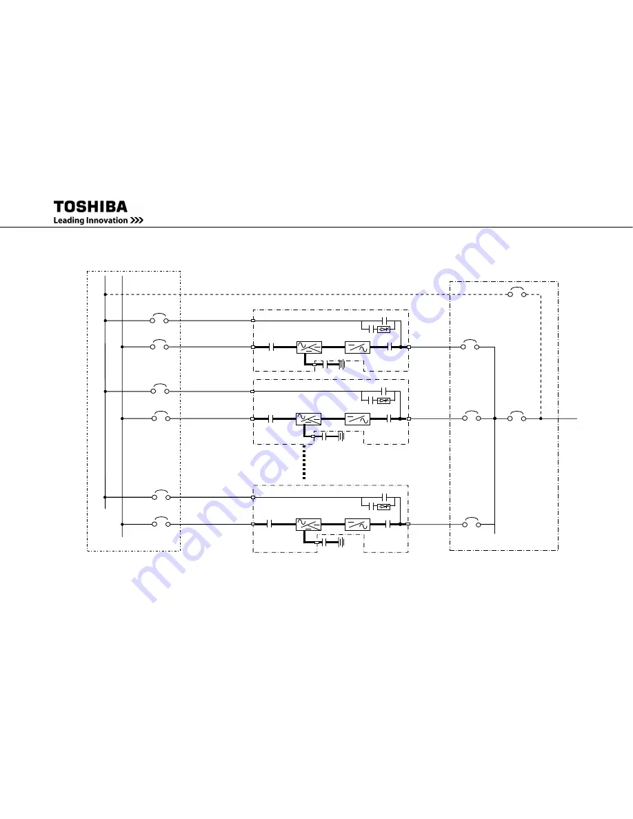
FIGURE 3.4
Diagram of Power Wire Connect
( Parallel Operation system connection )
Bypass
CB2
52L1
UPS
Breaker
Inverter
CB1
UPS-
1
Battery
52L2
UPS
Breaker
52C
Tie
Cabinet
UPS
Breaker
52L
n
(*1)
SMB
Maintenance
Bypass Breaker
Output
Breaker
52L
52S
Bypass
input
AC
input
Bypass
input
AC
input
Bypass
input
AC
input
AC
output
AC
output
AC
output
Converter
/Charger
UPS-
2
UPS-
n
(*1)
Bypas
s
CB
2
Inverter
CB1
Battery
52C
52S
Converter
/Charger
Bypass
CB
2
Inverter
CB1
Battery
52C
52S
Converter
/Charger
(*1) n: Maximum=4
Summary of Contents for T90S3S08KS6XSN
Page 21: ......
Page 23: ......
Page 25: ......
Page 27: ......
Page 29: ...G9000 Installation and Operation Manual ...
Page 31: ...G9000 Installation and Operation Manual ...
Page 98: ...G9000 Installation and Operation Manual 61 APPENDIX A Installation Planning Guides IPG ...
Page 99: ...62 G9000 Installation and Operation Manual ...
Page 100: ...G9000 Installation and Operation Manual 63 ...
Page 101: ...64 G9000 Installation and Operation Manual ...
Page 102: ......
Page 104: ......
Page 105: ......
Page 106: ......
Page 107: ......
Page 108: ......
Page 109: ......
Page 110: ......
Page 111: ......
Page 112: ......
Page 113: ......
Page 114: ......
Page 115: ......
Page 116: ......
Page 117: ......
Page 118: ......
Page 119: ......
Page 120: ......
Page 121: ......
Page 122: ......
Page 123: ......
Page 124: ......
Page 125: ......
Page 126: ......
Page 127: ......
Page 128: ......
Page 129: ......
Page 130: ......
Page 131: ......


