14
G9000 Installation and Operation Manual
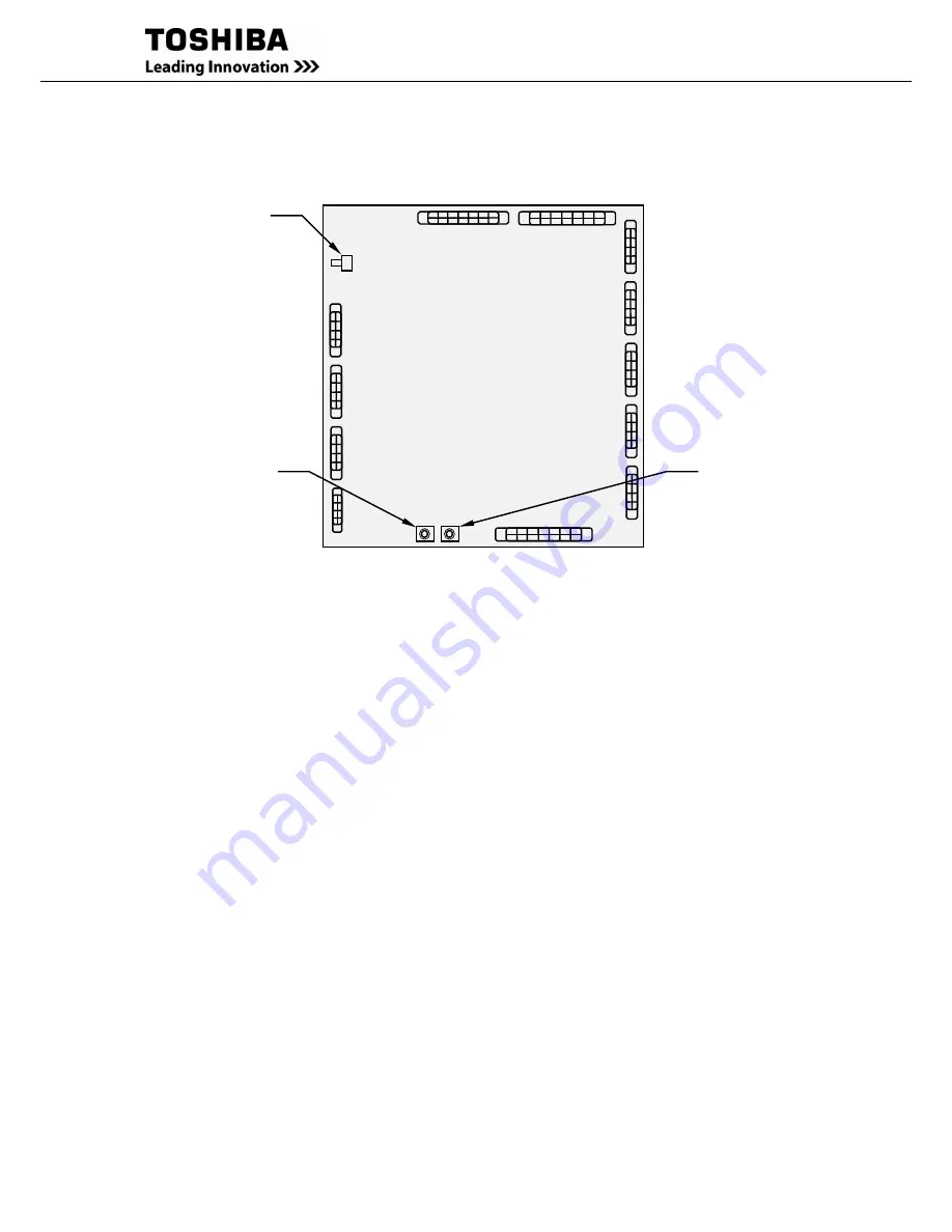
FIGURE 1.8
MAIN PCB UPGR-MA
Description of Figures 1.4 to 1.8:
1.
LCD Touch Panel Monitor Display
The Liquid Crystal Display (LCD) Touch Panel Monitor Display indicates power flow, measured
values and fault and error messages via user selectable display screens.
Refer to FIGURE 2.1 for details.
2.
Display PCB DPAU-81
(Figure 1.5):
Switches on DPAU-81 board
:
FOR SERVICE PERSONNEL ONLY
- (11) SW1 (RESET switch)
- (12) SW5 (TEST switch)
- (13) SW6 (MAINTENANCE switch)
3.
External I/F PCB IOAU-09
(Figure 1.6):
Signal I/F on IOAU-09 board
- (17) External contact signal terminal block
Refer to FIGURE 2.10 for details.
4.
Main PCB UPGR-M
(Figure 1.8):
Switches on UPGR-M board
:
FOR SERVICE PERSONNEL ONLY
- (11) SW1 (RESET switch)
- (14) SW2 (BOOT switch)
UPGR-M
A
11. SW1
RESET switch
14. SW2
BOOT switch
15. SW3
52L S/W
switch
Summary of Contents for T90S3S08KS6XSN
Page 21: ......
Page 23: ......
Page 25: ......
Page 27: ......
Page 29: ...G9000 Installation and Operation Manual ...
Page 31: ...G9000 Installation and Operation Manual ...
Page 98: ...G9000 Installation and Operation Manual 61 APPENDIX A Installation Planning Guides IPG ...
Page 99: ...62 G9000 Installation and Operation Manual ...
Page 100: ...G9000 Installation and Operation Manual 63 ...
Page 101: ...64 G9000 Installation and Operation Manual ...
Page 102: ......
Page 104: ......
Page 105: ......
Page 106: ......
Page 107: ......
Page 108: ......
Page 109: ......
Page 110: ......
Page 111: ......
Page 112: ......
Page 113: ......
Page 114: ......
Page 115: ......
Page 116: ......
Page 117: ......
Page 118: ......
Page 119: ......
Page 120: ......
Page 121: ......
Page 122: ......
Page 123: ......
Page 124: ......
Page 125: ......
Page 126: ......
Page 127: ......
Page 128: ......
Page 129: ......
Page 130: ......
Page 131: ......


