TOSHIBA G9000 UPS White Paper
© 2008 TOSHIBA INTERNATIONAL CORPORATION – INDUSTRIAL DIVISION
Page 5
/toshiba02/User2/UPSMKT/GENERAL/UPS/3 Phase Systems/White Papers/G9000 White Paper - multi-level converter.doc
UPSG9000WP081201
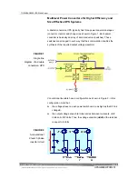
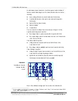
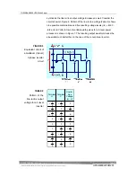
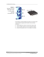
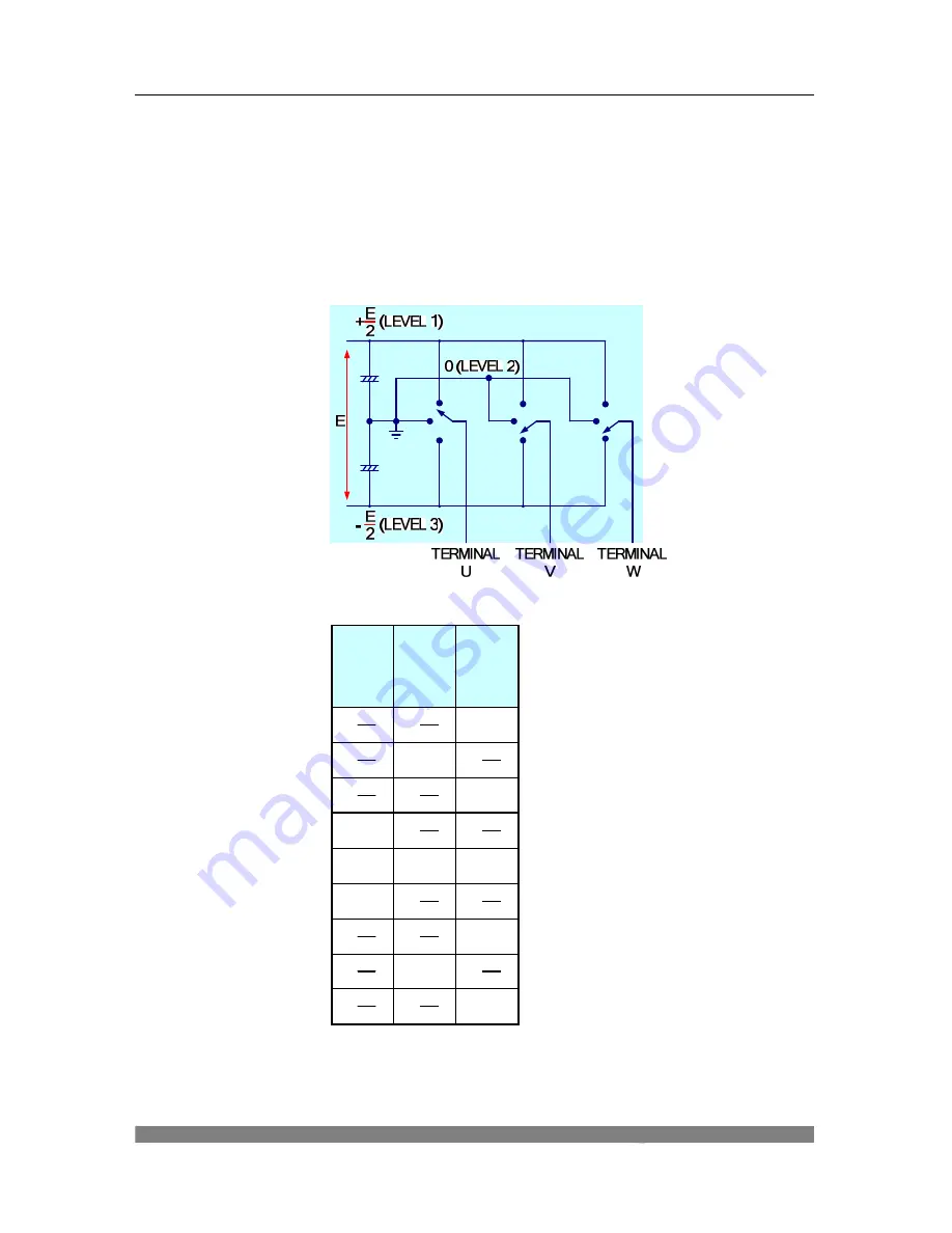
synthesize the line-to-line output voltage increases as well. Consider the
circuit shown in Figure 6. Pattern of the line-to-line voltage (Table 2) shows
nine possible combinations and five resulting voltage levels (+E, +E/2, 0,
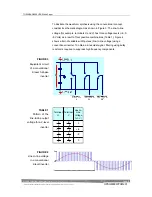
-E/2 and –E Volts). A train of variable-width pulses for a 3-level power
processor is shown in Figure 7. The resulting output waveform tracks the
sinusoidal much better than in the case of the conventional inverter.
E
E
2
2
E
E
2
2
E
E
2
2
E
E
2
2
E
E
2
2
E
E
2
2
E
E
2
2
E
E
2
2
-
-
0
-
-
0
-
+
- E
-
+
0
0
0
0
+
-
0
+
-
E
+
+
0
Terminal
U
Terminal
V
Line-to-
Line
Voltage
(U - V)
+
+
0
FIGURE 6
Equivalent circuit of
a multilevel (3-level)
3-phase inverter
circuit
TABLE 2
Pattern of the
line-to-line output
voltage for a 3-level
inverter
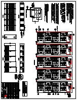
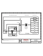
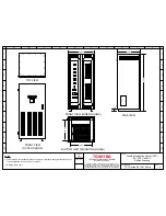
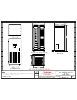
Summary of Contents for T90S3S08KS6XSN
Page 21: ......
Page 23: ......
Page 25: ......
Page 27: ......
Page 29: ...G9000 Installation and Operation Manual ...
Page 31: ...G9000 Installation and Operation Manual ...
Page 98: ...G9000 Installation and Operation Manual 61 APPENDIX A Installation Planning Guides IPG ...
Page 99: ...62 G9000 Installation and Operation Manual ...
Page 100: ...G9000 Installation and Operation Manual 63 ...
Page 101: ...64 G9000 Installation and Operation Manual ...
Page 102: ......
Page 104: ......
Page 105: ......
Page 106: ......
Page 107: ......
Page 108: ......
Page 109: ......
Page 110: ......
Page 111: ......
Page 112: ......
Page 113: ......
Page 114: ......
Page 115: ......
Page 116: ......
Page 117: ......
Page 118: ......
Page 119: ......
Page 120: ......
Page 121: ......
Page 122: ......
Page 123: ......
Page 124: ......
Page 125: ......
Page 126: ......
Page 127: ......
Page 128: ......
Page 129: ......
Page 130: ......
Page 131: ......

