TOSHIBA G9000 UPS White Paper
© 2008 TOSHIBA INTERNATIONAL CORPORATION – INDUSTRIAL DIVISION
Page 7
/toshiba02/User2/UPSMKT/GENERAL/UPS/3 Phase Systems/White Papers/G9000 White Paper - multi-level converter.doc
UPSG9000WP081201
Another benefit of the multilevel concept is the improvement of power
conversion efficiency. Due to the fact that three-level converters promote
lower voltage stress on power semiconductors, voltage ratings of
transistors and diodes can be lowered without compromise performance
and reliability.
For example, a 3-phase 480V power converter using a two-level circuit
requires a 1200V class IGBT, while a three-level circuit can be structured
using an IGBT voltage class of 600V. This flexibility in design allows the
selection of power semiconductors with better conduction and switching
characteristics.
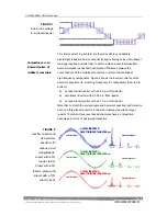
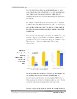
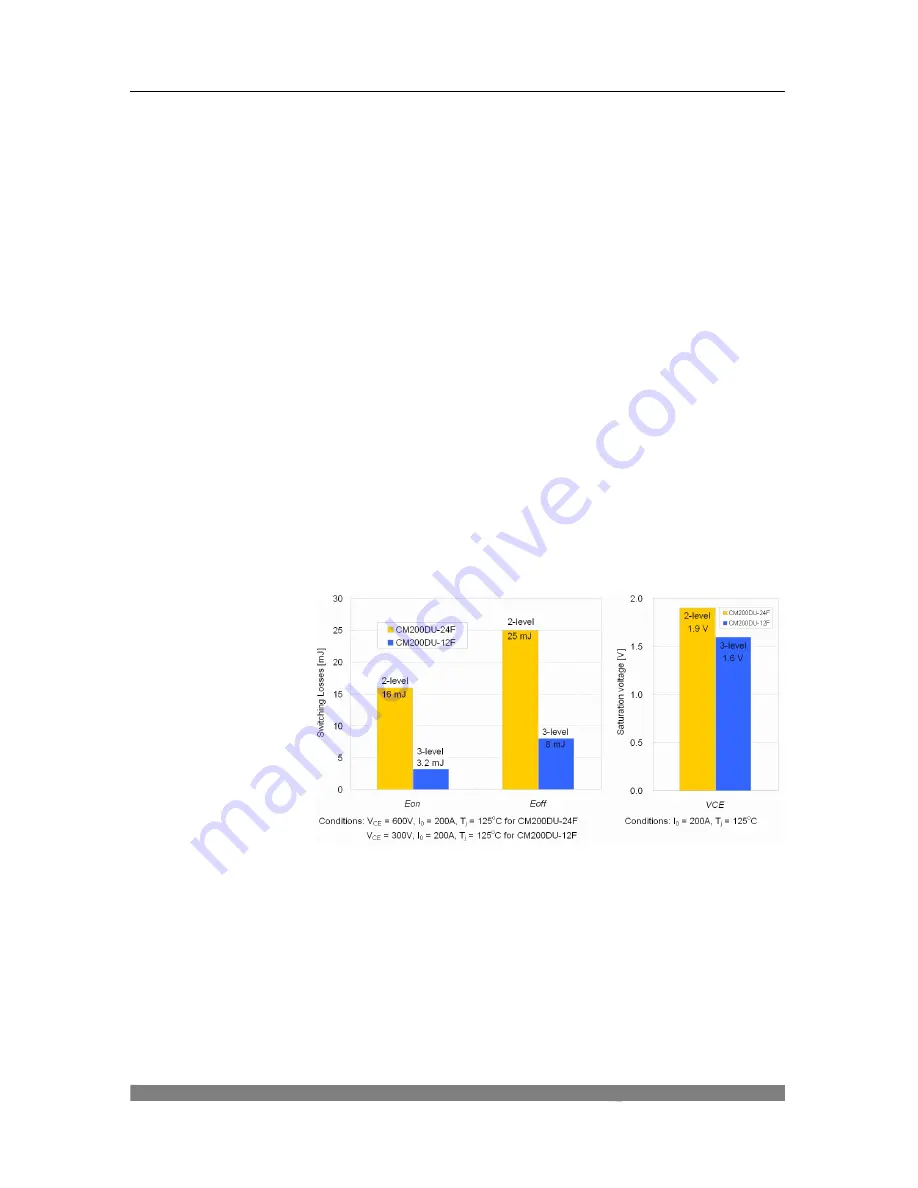
As an example, refer to the Figure 9 that shows the switching losses and
saturation voltage for a typical 1200V- and a 600V-class IGBT of same
generation from the same manufacturer. Although the saturation voltage is
almost the same, a 600V class IGBT exhibits better switching
characteristics.
Conduction losses are a function of the current in the semiconductor and
its saturation voltage. Thus, for a certain current level, from the
point-of-view of conduction losses, since the number of transistors in a
three-level power converter is the double as in a two-level circuit, this loss
component constitutes a disadvantage for a three-level circuit.
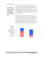
However, in terms of switching losses, the three-level topology shows off
FIGURE 9
Switching and
saturati on
characteristics for
a 1200V- and
a 600V-class
IGBT
Summary of Contents for T90S3S08KS6XSN
Page 21: ......
Page 23: ......
Page 25: ......
Page 27: ......
Page 29: ...G9000 Installation and Operation Manual ...
Page 31: ...G9000 Installation and Operation Manual ...
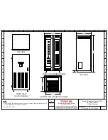
Page 98: ...G9000 Installation and Operation Manual 61 APPENDIX A Installation Planning Guides IPG ...
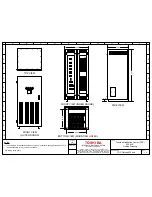
Page 99: ...62 G9000 Installation and Operation Manual ...
Page 100: ...G9000 Installation and Operation Manual 63 ...
Page 101: ...64 G9000 Installation and Operation Manual ...
Page 102: ......
Page 104: ......
Page 105: ......
Page 106: ......
Page 107: ......
Page 108: ......
Page 109: ......
Page 110: ......
Page 111: ......
Page 112: ......
Page 113: ......
Page 114: ......
Page 115: ......
Page 116: ......
Page 117: ......
Page 118: ......
Page 119: ......
Page 120: ......
Page 121: ......
Page 122: ......
Page 123: ......
Page 124: ......
Page 125: ......
Page 126: ......
Page 127: ......
Page 128: ......
Page 129: ......
Page 130: ......
Page 131: ......

