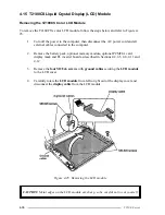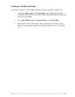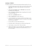
4-46
T2100 Series
4.19 T2100CT FL
Removing the FL
CAUTION
: When you remove the FL, be careful not to let any dust or other foreign
matter contaminate the LCD panel. Any contamination can affect the performance of
the FL.
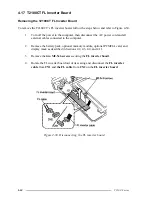
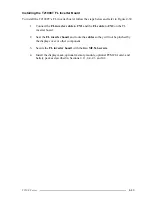
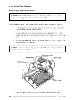
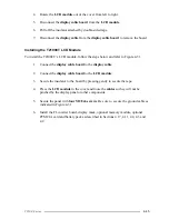
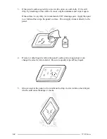
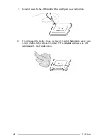
To remove the T2100CT’s FL, follow the steps below and refer to Figures 4-32 through 4-34.
1.
Turn off the power to the computer, then disconnect the AC power cord and all
external cables connected to the computer.
2.
Remove the battery pack, optional memory module, optional PCMCIA card,
display mask, FL inverter board, and display module as described in Sections 4.2,
4.3, 4.4, 4.11, 4.17 and 4.18.
3
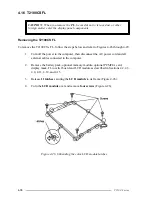
Place the LCD module face down and remove the
four M2.1x6 screws
(Figure 4-
32).
4.
Unsnap the five latches securing the
LCD frame
to the LCD module (Figure 4-
32).
CAUTION
: When you remove the LCD frame, eight hybrid ICs will be exposed at the
top/bottom of the LCD module. Use extreme care not to touch or jar these ICs.
Figure 4-32 Removing the T2100CT LCD module screws
Summary of Contents for T2100 Series
Page 5: ...T2100 Series 1 5 Figure 1 2 T2100 T2105 Series system unit configuration ...
Page 25: ...T2100 Series 2 3 Figure 2 1 Troubleshooting flowchart 1 2 ...
Page 114: ...3 64 T2100 Series ...
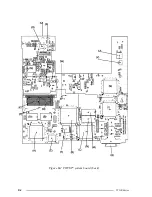
Page 168: ...B 2 T2100 Series Figure B 2 FHVSY system board back ...
Page 180: ...C 10 T2100 Series ...
Page 181: ...T2100 Series D 1 Appendix D USA Display Codes Table D 1 USA display codes ...
Page 182: ...D 2 T2100 Series ...
Page 196: ...H 2 T2100 Series ...
Page 198: ...I 2 T2100 Series ...


