T2100 Series
4-45
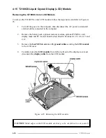
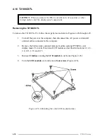
4.
Rotate the
LCD module
out of the cover from left to right.
5.
Disconnect the
display cable board
from the
LCD module
.
6.
Pull off the insulator attached by double-sided tape.
7.
Disconnect the
display cable
from the
display cable board
to remove the board.
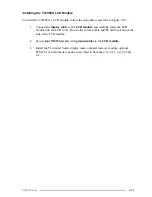
Installing the T2100CT LCD Module
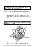
To install the T2100CT’s LCD module, follow the steps below and refer to Figure 4-31.
1.
Connect the
display cable board
to the
display cable
.
2.
Connect the
display cable board
to the
LCD module
.
3.
Secure the insulator to the board by pressing gently to secure the tape.
4.
Place the
LCD module
in the cover and route the
cables
so they will not be
pinched by the display panel or other components.
5.
Secure the panel with
four M2.5x6 screws
. Be sure to secure the ground cable as
indicated in Figure 4-31.
6.
Install the FL inverter board, display mask, optional memory module, optional
PCMCIA card and battery pack as described in Sections 4.17, 4.11, 4.4, 4.3 and
4.2.
Summary of Contents for T2100 Series
Page 5: ...T2100 Series 1 5 Figure 1 2 T2100 T2105 Series system unit configuration ...
Page 25: ...T2100 Series 2 3 Figure 2 1 Troubleshooting flowchart 1 2 ...
Page 114: ...3 64 T2100 Series ...
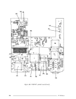
Page 168: ...B 2 T2100 Series Figure B 2 FHVSY system board back ...
Page 180: ...C 10 T2100 Series ...
Page 181: ...T2100 Series D 1 Appendix D USA Display Codes Table D 1 USA display codes ...
Page 182: ...D 2 T2100 Series ...
Page 196: ...H 2 T2100 Series ...
Page 198: ...I 2 T2100 Series ...


