4.7 Display Assembly
4 Replacement Procedures
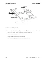
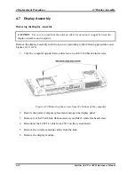
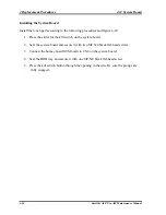
Figure 4-20 Removing the display assembly
Installing the Display Assembly
Install the display assembly according to the following procedures and Figures 4-19, 4-20.
1. Place the display panel in their correct position and push the wireless antenna cable
into the hole.
2. Connect the LCD/FL cable to CN13 on the system board and fix it with one M2x3
white flat-head screw.
3. Securing display assembly with four M2.5x4 black flat-head screws.
4. Close the display panel and turn the computer upside down and fix it with two
M2.5x20 black bind screws.
Satellite A60/ Pro A60 Maintenance Manual
4-31
Summary of Contents for Satellite Pro A60 Series
Page 10: ...x Satellite A60 Pro A60 Maintenance Manual ...
Page 11: ...Chapter 1 Hardware Overview ...
Page 12: ...1 Hardware Overview 1 ii Satellite A60 Pro A60 Maintenance Manual ...
Page 35: ...2 Troubleshooting 2 Chapter 2 Troubleshooting 2 i Satellite A60 Pro A60 Maintenance Manual ...
Page 65: ...Chapter 3 Diagnostic Programs ...
Page 68: ......
Page 134: ...Chapter 4 Replacement Procedures 4 1 ...
Page 135: ...4 Replacement Procedures 4 ii Satellite A60 Pro A60 Maintenance Manual ...
Page 141: ......
Page 202: ...6000 1 次 Appendices ...
Page 203: ...Appendices App ii Satellite A60 Pro A60 Maintenance Manual ...
Page 211: ...Appendices Apx A Handling the LCD Module A 6 Satellite A60 Pro A60 Maintenance Manual ...
Page 221: ......
Page 223: ......
Page 225: ......
Page 229: ......
Page 231: ......
Page 235: ......
Page 237: ......
Page 239: ......
Page 250: ......
Page 252: ......
Page 254: ......
Page 256: ......
Page 262: ......
Page 264: ......

