4 Replacement Procedures
4.8 Top Cover
4.8 Top
Cover
Removing the Top Cover
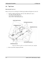
Remove the top cover according to the following procedures and Figures 4-21 and 4-22.
1. Turn the computer upside down, and remove the following 25 screws:
- Two M2.5x14 black bind screws
- Twelve M2.5x6 black bind screws
- Eleven M2.5x3 black flat-head screws
Figure 4-21 Removing the screws from the bottom of the computer
2. Restore the normal computer placement.
4-32
Satellite A60/ Pro A60 Maintenance Manual
Summary of Contents for Satellite Pro A60 Series
Page 10: ...x Satellite A60 Pro A60 Maintenance Manual ...
Page 11: ...Chapter 1 Hardware Overview ...
Page 12: ...1 Hardware Overview 1 ii Satellite A60 Pro A60 Maintenance Manual ...
Page 35: ...2 Troubleshooting 2 Chapter 2 Troubleshooting 2 i Satellite A60 Pro A60 Maintenance Manual ...
Page 65: ...Chapter 3 Diagnostic Programs ...
Page 68: ......
Page 134: ...Chapter 4 Replacement Procedures 4 1 ...
Page 135: ...4 Replacement Procedures 4 ii Satellite A60 Pro A60 Maintenance Manual ...
Page 141: ......
Page 202: ...6000 1 次 Appendices ...
Page 203: ...Appendices App ii Satellite A60 Pro A60 Maintenance Manual ...
Page 211: ...Appendices Apx A Handling the LCD Module A 6 Satellite A60 Pro A60 Maintenance Manual ...
Page 221: ......
Page 223: ......
Page 225: ......
Page 229: ......
Page 231: ......
Page 235: ......
Page 237: ......
Page 239: ......
Page 250: ......
Page 252: ......
Page 254: ......
Page 256: ......
Page 262: ......
Page 264: ......

