– 104 –
No. Part name
Procedure
Remarks
g
Electrical
part
replacement
(continued)
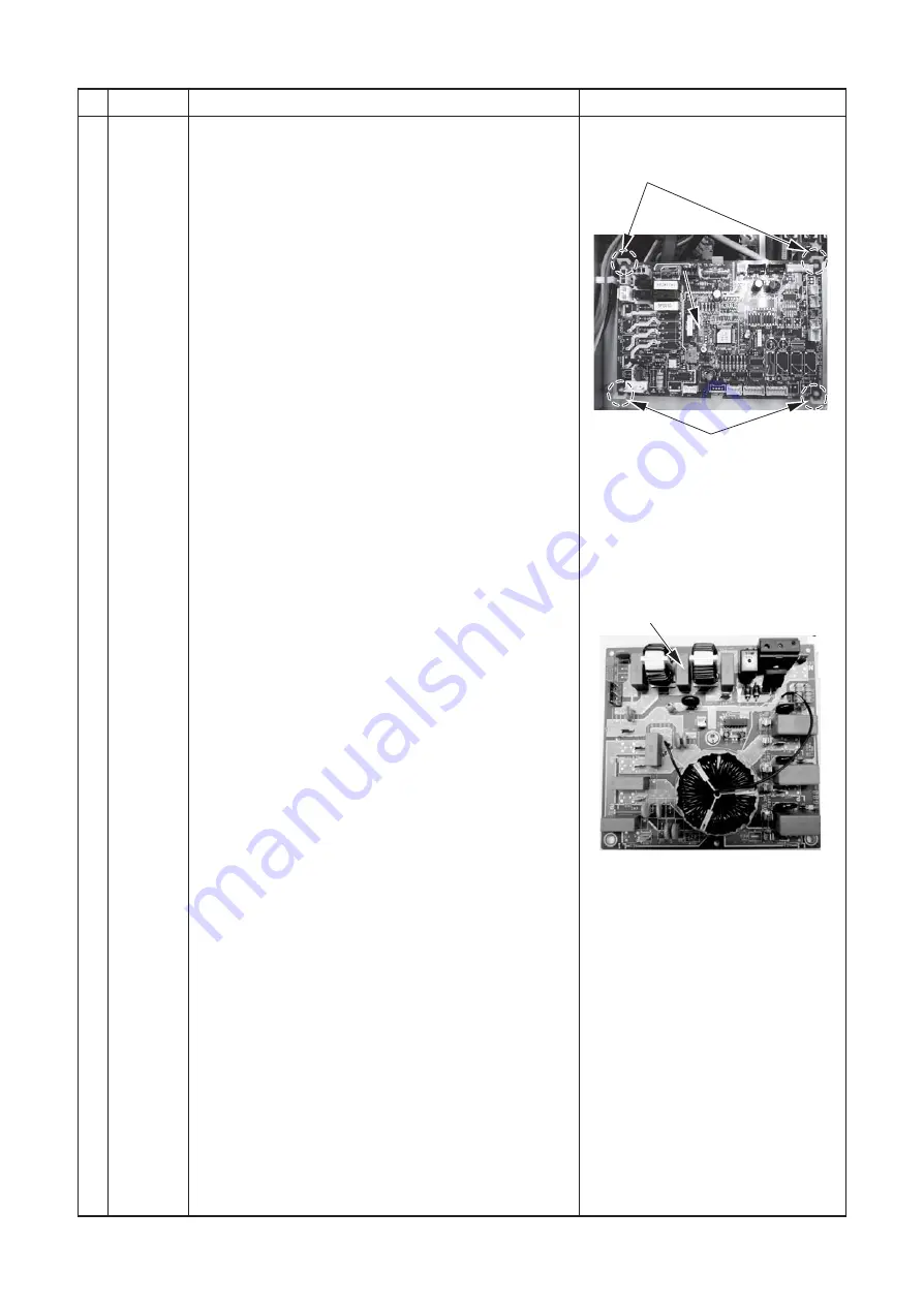
3. Interface (CDB) P.C. board
1) Following to work of item to 2) of 1 of
g
.
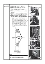
2) Remove the Interface (CDB) P.C. board connectors (18
places)
CN603 ... TD sensor (3P: White, tube: Red)
CN602 ... TO sensor (2P: Yellow, tube: Red)
CN601 ... TE sensor (2P: White, tube: Black)
CN600 ... TS sensor (3P: White, tube: Gray)
CN604 ... TL sensor (2P: White, tube: Blue)
CN700 ... 4-way valve coil (3P: Yellow)
CN702 ... 2-way valve coil (2P: White)
CN710 ... PMV coil 1 (6P: White)
CN711 ... PMV coil 2 (6P: White)
CN606 ... Pressure sensor (4P: White)
CN609 ... Case thermostat (2P: Blue)
CN802 ... FAN-IPDU board connector (5P: Red)
CN02 ..... Noise filter board connector (3P: Red)
CN608 ... Noise filter board connector (2P: White)
CN690 ... A3-IPDU connector (3P: Green)
CN708 ... Magnetic switch connector (2P: Blue)
CN01 ..... Indoor/outdoor terminal block connector
(3P: White)
CN807 ... Display board connector (10P: White)
3) Remove the Interface (CDB) P.C. board. (4 supporters)
4) Attach the new Interface (CDB) P.C. board to the
inverter box.
4. Noise filter P.C. board
1) Following to work of item to 2) of 1 of
g
.
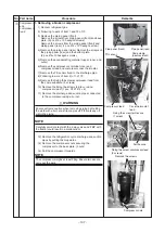
2) Remove the connectors (3 places) from the noise filter
P.C. board.
CN22 ..... CN500 of the FAN-IPDU P.C. board connector
(2P: Red)
CN50 ..... CN608 of the CDB P.C. board connector
(2P: White)
CN51 ..... CN602 of the FAN-IPDU P.C. board connector
(2P: Black)
3) Remove the lead wires (10 places) connected to the
noise filter P.C. board.
CN05 ..... Power terminal block connector (Red)
CN06 ..... Power terminal block connector (White)
CN07 ..... Power terminal block connector (Black)
CN08 ..... Power terminal block connector (Gray)
CN09 ..... Ground connector (Brown)
CN10 ..... CN02 of the CDB P.C. board connector (Red)
CN19 ..... CN02 of the CDB P.C. board connector
(Gray)
CN16 ..... Power relay connector (Red)
CN17 ..... A3-IPDU P.C. board connector (White)
CN18 ..... Power relay connector (Black)
4) Remove the earth screw on the noise filter P.C. board.
5) Remove the noise filter P.C. board. (3 supporters)
6) Attach the new noise filter P.C. board to the inverter
box.
Supporters
Interface (CDB)
Interface (CDB)
P.C. Board
P.C. Board
Interface (CDB)
P.C. Board
Noise filter P.C. board
Supporters

