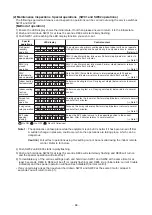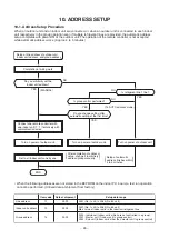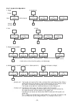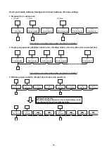
– 102 –
No. Part name
Procedure
Remarks
g
Electrical
part
replacement
WARNING
There is a risk of electric shock because the voltage
remains in the electrolytic capacitor on the P.C. board for a
while after the power is turned off. Make sure that the
voltage does not remain with a tester before
disassembling the inverter assembly.
When replacing any electrical parts please ensure to tighten
the screws using the following tightening torque
requirements. Note that use of the product with insufficiently
tightened screws could cause a malfunction.
M3 screw: 0.55 N•m
M4 screw: 1.20 N•m
M5 screw: 1.80 N•m
M6 screw: 2.40 N•m
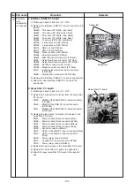
1. A3-IPDU P.C. board
1) Following to work of item to 3) of 1 of
c
.
2) Loosen the screws (upper and lower) that fix the
inverter cover and inverter box together.
(2 pcs, Ø4 × 8)
3) Remove the A3-IPDU P.C. board and other P.C. board
connectors. (2 pcs)
CN101 ... FAN-IPDU P.C. board and CN502 connector
(2P: White)
CN852 ... FAN-IPDU P.C. board and CN504 connector
(5P: White)
4) Remove the leads connected to the A3-IPDU P.C.
board (9 places)
CN01 ..... Power relay connector (Red)
CN02 ..... CN12 of the noise filter P.C. board connector
(White)
CN03 ..... Power relay connector (Black)
CN04 ..... PTC thermistor connector (Red)
CN203 ... Compressor connector (Red)
CN202 ... Compressor connector (White)
CN201 ... Compressor connector (Black)
CN09 ..... Reactor (CH90) connector
CN10 ..... Reactor (CH90) connector
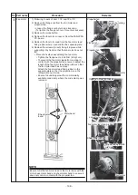
5) Remove the screws fixing the heat sink to the A3-IPDU
P.C. board. (4 pcs, Ø4 × 15)
6) Remove the A3-IPDU P.C. board. (2 supporters)
7) Set the dip switch (SW800) of the new A3-IPDU P.C.
board as follows.
Inverter box
Inverter cover
Inverter box and
Inverter cover
fixing screw
Inverter box
Inverter cover
Inverter box and
Inverter cover
fixing screw
PCT thermistor
Power relay
Noise filter
P.C. board
CDB P.C. board
CDB P.C. board
Fuse
A3-IPDU P.C. board
A3-IPDU P.C. board
Ø4
4 × 15
15
screws
screws
Ø4 × 15
screws
Radiator grease
application locations
FAN-IDPU
FAN-IDPU
P.C. board
P.C. board
CDB P.C. board
A3-IPDU P.C. board
A3-IPDU P.C. board
FAN-IDPU
P.C. board
ON
1
2
ON OFF
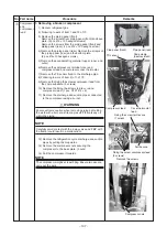
8) Apply radiator grease to the rear of the new
A3-IPDU P.C. board where it will be fixed to the heat
sink and then attach to the heat sink.
Note that insufficient radiator grease could result in
insufficient heat dissipation and then a malfunction.

