Basic Installation and Operation Guide
JK 400 Series Fixed Controllers
TOSHIBA
19
E. Operating Handle
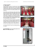
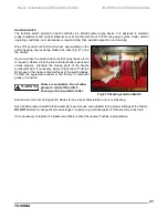
The external operating handle shown in Fig. 29 is used to control the operation
of the isolation switch.
Moving the
handle upward turns the switch on, thus
applying incoming power to the main current-limiting fuses.
Moving the handle down opens the isolation switch, de
-energizing all medium
voltage incoming power to the controller compartment. At the same time, an
automatic shutter within the switch closes, providing an effective barrier between
the controller compartment and the incoming supply. The opening of the switch
also causes the line side of the power fuses to be grounded.
Further details on the isolat
ion switch and external operating handle can be
found in the Maintenance section.
Fig. 29 Operating Handle
F. Interlocks - Mechanical
a. Door Interlock
A mechanical interlock is provided to prevent opening or closing the medium
voltage compartment door unless the switch operating handle is off (
Fig.
30).
Fig. 30 Door Interlock

