Basic Installation and Operation Guide
JK 400 Series Fixed Controllers
TOSHIBA
15
GENERAL DESCRIPTION
Toshiba JK 400 ampere medium voltage controllers are AC
general-
purpose NEMA Class E
2 controllers designed for
applications at utilization voltages ranging from 2.3 through 6.6
kV. They are normally used to control motor loads, although
other types of loads such as
variable frequency drives (VFDs),
transformers and capacitors are possible.
Construction
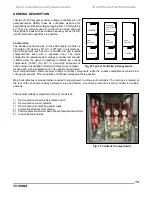
The standard enclosure size for the 400 ampere controller is
30" wide by 36" deep by 46”, 60” or 90" high. In a typical one-
high arrangement, each section is divided into two isolated
compartments, each with a separate door. The lower
compartment contains medium voltage controller components
(>600V) while the upper compartment contains low voltage
components (<600V) (
Fig. 2
2). In a two-high arrangement,
each enclosure is divided vertically into three major compart-
Fig. 22 Typical Controller Arrangements
ments, each with a separate door. The uppermost and lower-
most compartments contain medium voltage controller components while the middle compartment contains low
voltage components
. Other variations of this basic arrangem
ent are possible.
Main horizontal bus is provided when required to supply power to a line
-up of controllers. The main bus is located at
the rear of
t
he enclosure midway between the top and bottom. A common ground bus is also provided for multiple
sections.
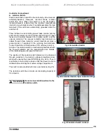
The medium voltage compartment (
Fig. 2
3) consists of:
1)
Fix
-mounted non-load break isolation switch
2)
Fix
-mounted vacuum contactor
3)
Fix
-mounted current-limiting power fuses
4) Current transformers for metering
5) Control power transformer and optional potential transformer
6) Load cable terminations
Fig. 23 Controller Compartment
F
F
O
N
ISOLATION
POWER
SWITCH
O
O
F
F
POWER
ISOLATION
N
O
SWITCH
STARTER
LOW
VOLTAGE
F
F
O
SWITCH
POWER
ISOLATION
O
N
BLANK OR
ADDITIONAL
MV
COMPONENTS
F
F
O
ISOLATION
POWER
SWITCH
N
O
STARTER
STARTER
STARTER
LOW
VOLTAGE
LOW
VOLTAGE

