Basic Installation and Operation Guide
JK 400 Series Fixed Controllers
TOSHIBA
8
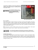
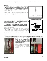
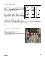
Fig. 11 Main Bus Splice Connections - 1200A Main Bus
NOTE:
Covers and braces supplied only for protection during shipment should not be replaced.
All debris and tools should be removed from each compartment as cabling is completed.
Remove part number identification or any label on the splice bus before installation.
Tighten and torque the bolts for all bus splice connections and other bus if loosened
during installation of the bus splice.
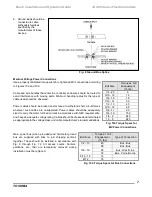
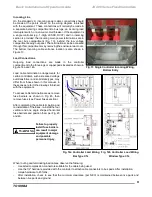
Fig. 12 Main Bus Splice Connections - 2000A
(Consult Factory for 3000A Main Bus Splice)

