Basic Installation and Operation Guide
JK 400 Series Fixed Controllers
TOSHIBA
29
The information presented here is intended to cover preventive maintenance only. It does not cover major
rework or repair. The following
MAINTENANCE SHOULD BE PERFORMED AT LEAST ANNUALLY
or more
frequently depending on operating conditions.
General Inspection
Thoroughly clean the equipment, removing all dust, dirt, and other accumulations. Wipe insulators clean using
a clean, dry cloth. Do not use petroleum-based solvents or cleaners.
Check for any signs of moisture inside the enclosure. If there are signs of dripping water entering the
enclosure, eliminate the source. Thoroughly dry any insulation which shows signs of wetness and repeat the
dielectric test procedure given in the PRE-ENE
RGIZATION CHECK. Replace insulators, if necessary.
Check for any signs of rusted or corroded parts.
Check for free movement of all moving parts and mechanisms. Lubricate, if necessary, with Toshiba B9
grease.
Grease is conductive. Do not apply grease to electrical insulation.
Electrical Joints
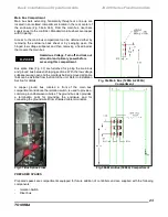
Examine all visible terminals and joints for signs of
overheating (Fig.
42). An overheated connection will
appear discolored. Be suspicious of any conducting joint
which has a darker color than other similar joints.
Check all bolted connections for tightness. The proper
torque is dependent on the size of the hardware and the
materials used. As a general guide, use the following
Fig. 43.
The values apply to metal-to-metal joints (e.g.
copper-to-copper). When applying torque to a bolt
threaded into an insert, molded into a plastic part, use
approximately 2/3 the torque shown.
Fig. 43 Torque Specs for
MV Power Connections
Fig. 42 Check Electrical Joints
Bolt Size
Torque at
Full
Engagement
(ft - lbs)
1/4 - 20
6
3/16 - 18
12
3/8 - 16
18
7/16
- 14
30
1/2 - 13
45
9/16 - 12
68
5/8 - 11
90
3/4 - 10
150
7/8
- 9
240
1.0 - 8
245
WARNING

