background image

Adjusting the TJC-spray Volume

1.

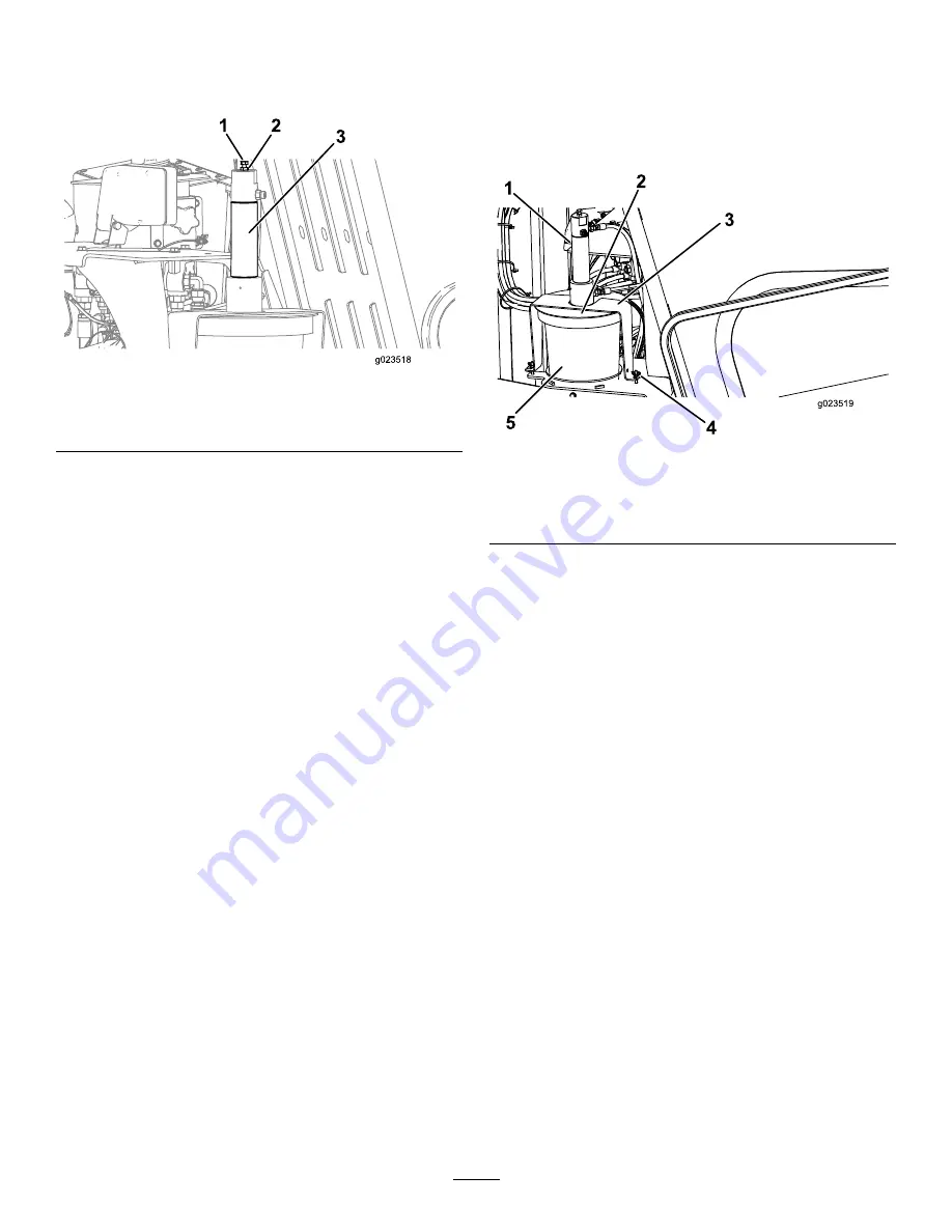
Loosen the jam nut on the adjustment bolt located on
top of the TJC-applicator piston (

Figure 88

).

Figure 88

1.

Adjustment bolt

3.

TJC-applicator piston

2.

Jam nut

2.

Adjust the bolts as follows:

To increase the applied volume of compound,
thread the bolt out (up).

To decrease the applied volume of compound,
thread the bolt in (down).

3.

When you have attained the desired application volume,
tighten the jam nut to secure the adjustment.

Filling the TJC Applicator

1.

Stop the machine and stop the engine.

2.

Open the stake-down-guard door.

3.

Loosen the wing nuts securing the cover straps to the
machine (

Figure 89

).

Figure 89

1.

TJC-applicator piston

4.

Wingnut

2.

Cover

5.

TJC bucket

3.

Strap

4.

Rotate the cover and pull the cover straps off the
retaining bolts (

Figure 89

).

5.

Lift the cover assembly off and out of the empty
thread-joint-compound bucket (

Figure 89

).

6.

Replace the empty bucket with a new full bucket.

7.

Place the plunger into the new bucket and lower the
cover assembly onto the bucket (

Figure 89

).

8.

Slide the cover straps over the retaining bolts, and
rotate the cover to seat the straps on the bolts (

Figure

89

).

9.

Tighten the wing nuts.

75


Summary of Contents for 23825

Page 1: ...Form No 3401 924 Rev A 4045 Directional Drill Model No 23825 Serial No 313000501 and Up Model No 23825 Serial No 314000501 and Up Register at www Toro com Original Instructions EN 3401 924 A ...

Page 2: ...liance information refer to your Compliance Statement Addendum that pertains to your country Introduction This machine is a directional drill intended for underground drilling and pullback operation for utility lines including electrical gas communication water etc It is designed to operate a wide variety of attachments each of which perform a specialized function Read this information carefully t...

Page 3: ...r cleaning System 85 Servicing the Engine Oil and Filter 87 Adjusting the Valve Clearance 89 Fuel System Maintenance 90 Draining Water from the Fuel Filter 90 Draining Water from the Fuel Tank 90 Priming the Fuel System 91 Replacing the Fuel Filters 91 Checking the Fuel Lines and Connections 92 Draining and Cleaning the Fuel Tank 92 Electrical System Maintenance 93 Servicing the Battery 93 Chargin...

Page 4: ...y signs All operators and mechanics should be trained The owner is responsible for training the users Do not let children or untrained people operate or service the equipment Preparation Evaluate the terrain to determine what accessories and attachments are needed to properly and safely perform the job Only use accessories and attachments approved by the manufacturer Wear appropriate clothing incl...

Page 5: ...g or unloading the machine onto a trailer Watch for traffic when crossing roadways Check for overhead clearances i e branches doorways electrical wires before driving under any objects and do not contact them Use care when driving the machine on soft or unstable ground Note Soft or uneven ground can reduce stability When driving on a slope the operator should be up slope from the machine Note The ...

Page 6: ...the machine its working devices auxiliary equipment or swinging falling equipment The following illustration displays the safe distance required by all individuals while drilling Figure 4 Drilling Danger Zone 1 3 m 10 ft safety distance 3 1 8 m 6 ft safety distance 2 Pedestrian safety bar Drilling Near Utility Lines Important Before operating in an area with high voltage lines or cables contact a ...

Page 7: ...r will trip but to ensure your safety consider that the machine may be conducting electricity Do not attempt to leave the machine Important You will be safe as long as you do not leave the seat of the machine Touching any part of the machine may ground you Do not allow another individual to touch or approach the machine when charged The alarm may sound if a communication line is broken but until y...

Page 8: ...or other debris build up Clean up oil or fuel spillage Allow the machine to cool before storing Use extra care when handling fuels They are flammable and vapors are explosive Use only an approved container Do not remove the fuel cap or add fuel when the engine is running Allow the engine to cool before refueling Do not smoke while refueling the machine Do not refuel the machine indoors Do not stor...

Page 9: ...moking 7 Wear eye protection explosive gases can cause blindness and other injuries 3 Caustic liquid chemical burn hazard 8 Battery acid can cause blindness or severe burns 4 Wear eye protection 9 Flush eyes immediately with water and get medical help fast 5 Read the Operator s Manual 10 Contains lead do not discard 117 2718 125 6118 1 Crushing hazard machine movement read the Operator s Manual 12...

Page 10: ...or s Manual 125 6694 1 Tie down point 125 8473 1 Explosion hazard wear eye protection 3 Fire hazard keep open flames away 2 Caustic liquid chemical burn hazard rinse affected area and seek medical assistance 4 Poison hazard do not tamper with the battery 10 ...

Page 11: ... do not use tools read the Operator s Manual 125 6119 1 Entanglement hazard keep away from moving objects 125 6126 1 Entanglement hazard keep away from moving parts 125 6131 1 Warning stay at least 3 m 10 ft away from the machine 11 ...

Page 12: ...nd under any part of the machine 125 6128 1 High pressure fluid hazard injection into the body read the Operator s Manual before performing maintenance 125 6130 1 Warning read the Operator s Manual stay at least 3 m 10 ft away from the front and rear of the machine and 1 8 m 6 ft away from the sides of the machine 12 ...

Page 13: ...hine will be energized with electrical power 125 6111 1 Stake up 6 Stake up 2 Stake down 7 Stake spin counterclockwise 3 Stake spin counterclockwise 8 Stake down 4 Stake spin clockwise 9 Stake spin clockwise 5 Left stake 10 Right stake 125 6123 1 Load pipes from back row first 125 6124 1 Center the pipe joint between the upper makeup breakout wrench and lower wrenches stationary wrench 13 ...

Page 14: ...ng hazard of hand and foot keep hands and feet away 125 6116 1 Falling hazard do not move the machine when someone is in the operator s position 125 6140 1 Rotate the chair 125 6152 1 Move seat forwards and backwards 14 ...

Page 15: ...ry wrench Mode II spin drill spindle clockwise 6 Unlock exit side lockout 18 Mode I left trigger released extends pipe gripper toward pipe holder left trigger pressed closes lower wrench stationary wrench Mode II spin drill spindle counterclockwise 7 Reset exit side lockout 19 Mode I left trigger released lowers pipe elevator left trigger pressed opens upper wrench makeup breakout wrench Mode II l...

Page 16: ... wrench makeup breakout wrench 8 Unlock exit side lockout 21 Mode I left trigger released raises pipe elevator left trigger pressed closes upper wrench makeup breakout wrench Mode II left trigger released extends pipe gripper toward pipe holder left trigger pressed closes upper wrench makeup breakout wrench 9 Reset exit side lockout 22 With trigger released rock forward to rotate basket toward pip...

Page 17: ...pindle counterclockwise Mode II left trigger pressed close the lower wrench stationary wrench left trigger released lower the pipe elevator 4 Press and hold for maximum drilling fluid pressure release to stop the flow 9 Thrust the drill carriage forward 5 Press to turn the drilling fluid pump on or off 10 Pull the drill carriage rearward 125 1641 1 Forward left 6 Forward right 2 Increase rpm 7 Hig...

Page 18: ...Hot surface keep away from hot surfaces 125 6141 1 Engine heating light 4 Engine start 2 Engine stop 5 Drill pendant receptacle 3 Engine run 6 Drive pendant receptacle 0 0 0 0 0 0 0 0 0 0 0 0 125 6157 1 Disconnect the battery power 3 On Start 2 Off Stop 4 Read the Operator s Manual 18 ...

Page 19: ...t operate the machine unless you are trained 5 Warning wear hearing protection 3 Warning keep bystanders away from the machine 6 Explosion hazard electrical shock hazard do not dig before calling local utilities 125 6117 1 Falling hazard do not stand on the machine while it is moving 125 6139 1 Lift point and tie down point 125 6135 19 ...

Page 20: ...rward carriage 14 Reverse cam rotation 5 Reverse right track reverse carriage 15 Forward toward operator cam rotation 6 Tighten lower wrench stationary wrench 16 Tighten pipe grip 7 Loosen lower wrench stationary wrench 17 Loosen pipe grip 8 Tighten upper wrench makeup breakout wrench 18 Reverse drill spindle 9 Loosen upper wrench 19 Forward toward operator drill spindle 10 Wrench breakout for upp...

Page 21: ...Product Overview Figure 5 1 Drill carriage 6 Front hood 2 Zap alert strobe 7 Right stabilizer 3 Cab 8 Rear access door 4 Monitor 9 Rear hood 5 Track 10 Thrust frame 21 ...

Page 22: ...Figure 6 1 Stake down cage 5 Rear control panel 2 Pipe holder 6 Left stabilizer 3 Pedestrian safety bar 7 Stake down plate 4 Drilling fluid pump inlet 22 ...

Page 23: ...Figure 7 1 Cab 5 Upper wrench makeup breakout wrench 2 Thrust frame 6 Lower wrench stationary wrench 3 Drill carriage 7 Pipe wiper 4 Drill spindle 23 ...

Page 24: ...oystick Operator controls Covers The covers protect the operator controls from adverse weather conditions such as rain wind sunlight etc Remove them before using the machine and replace them before leaving the machine for the day Each cover is secured with 2 screws as shown in Figure 9 Figure 9 1 Screws 2 Covers Operator platform Latch The operator platform swings out away from the machine making ...

Page 25: ...e 2 control layouts that the operator can choose from consist of the following Mode I This function places the drilling functions on the right joystick while the left joystick operates the pipe loader and the wrench functions Figure 13 Press button number 4 to select this function Figure 13 Mode II This function splits the drilling wrench and pipe loading between the left and right joysticks Figur...

Page 26: ...rilling fluid gallons used Main Operating Screen To access this screen press button 4 or the down arrow on the Machine information Screen page 26 The main operating screen displays the engine speed rpm gauge the fuel quantity gauge the engine temperature gauge the rod row selector thrust control and horsepower control Figure 15 The low fuel indicator lights up on the main operating screen when the...

Page 27: ... pressure psi 7 Drilling fluid flow rate gpm 4 Drilling fault indicator 8 Carriage pressure gauge psi Main Drill Functions Displayed in Torque Screen To access this screen press the down arrow on the Main Drill Functions Displayed in Pressure Screen page 27 This screen provides measurements on rotary torque in ft lbs drilling fluid pressure in psi carriage force in lbs and drilling fluid flow rate...

Page 28: ...l rotation speed 2 Right arrow increase speed 4 Left arrow decrease speed Thrust control Screen This screen allows the user to increase or decrease the thrust output of the machine To access this screen press button number 3 on the Main Operating Screen page 26 To change the thrust output of the machine perform the following 1 Press button number 1 to increase the torque output or button number 3 ...

Page 29: ...n number 3 to activate 90 engine speed rpm as shown in Figure 20 Press button number 4 to return to the main operating screen Figure 20 1 2 3 4 5 6 7 8 OK ESC g025086 1 2 3 4 Figure 20 Horsepower control Screen 1 60 engine speed rpm 3 90 engine speed rpm 2 75 engine speed rpm 4 Return to the previous screen Pipe row selector Screen This screen allows you to select the row of pipe s that you want t...

Page 30: ... 5 6 7 8 9 Figure 22 Main selection Screen 1 Machine information 6 Clear service reminder 2 Lubrication and maintenance chart 7 Control joystick selection 3 Loader calibration 8 Error codes 4 Diagnose and adjust parameters 9 Return to the Main Operating Screen 5 Air hammer control Lubrication and Maintenance Screens To access this screen press button number 2 on the Main selection Screen page 30 T...

Page 31: ... to see the previous engine error Figure 28 Note If there are no drilling errors or engine errors press the OK button to exit this screen Figure 28 1 2 3 4 5 6 7 8 OK ESC g025089 1 2 3 4 5 Figure 28 Error Codes Screen 1 Total number of drill errors 4 Previous engine error 2 Next engine error 5 Total number of engine errors 3 Next drill error Diagnose and Adjust Parameters Screen To access this scr...

Page 32: ...alibrate loader cam 3 Return to the Main selection Screen 2 Calibrate loader arm Loader cam calibration Screen To access this screen press button number 1 on the Loader calibration Screen page 32 This screen allows the user to set the row positions for the pipe holder Press the following buttons to set the desired position Button 1 Set position 1 Figure 30 Button 2 Set position 2 Figure 30 Button ...

Page 33: ...on 2 Set arm Home Figure 31 Figure 31 Loader arm calibration Screen 1 Set arm In 3 Return to the previous screen 2 Set arm Home Clear service reminder Screen To access this screen press button number 7 on the Main selection Screen page 30 To clear a service reminder enter the 8 digit PIN 13236573 into this screen Figure 32 1 2 3 4 5 6 7 8 OK ESC g025091 Figure 32 Enter PIN Screen After entering th...

Page 34: ...r upper wrench Thrust percentage and output Pullback percentage and output On and Off indicators for two speed seat switch cam rotation carriage back and arms out Auxiliary activations Screen Press the down arrow on the Rotary and Carriage service Screen page 34 to access this screen The auxiliary activations screen Figure 35 provides the following information Figure 35 On and Off indicators for c...

Page 35: ...n and Off indicators for seat switch and setup Drilling fluid percentage and output Track drive information Screen Press the down arrow on the Drilling fluid information Screen page 35 to access this screen The track drive information screen Figure 37 provides the following information Figure 37 Output for left forward left reverse right forward and right reverse movements of the track drive Front...

Page 36: ... lockout transmitter is too low to transmit Stop drilling operations and fix the problem with the transmitter before continuing Engine start Button Press this button Figure 38 to start the engine The key switch on the rear control panel must be in the On position Engine stop Button Press this button Figure 38 to immediately stop the engine and all drilling operations You must pull this button out ...

Page 37: ...Front Button Left trigger pressed press this button to resume the previously set auto drill speed Press and hold this button to increase the auto drill speed Left trigger released press this button to open the pipe gripper Rear Button Left trigger pressed press this button to set the auto drill speed Press and hold this button to decrease the auto drill speed Left trigger released press this butto...

Page 38: ...o rotate the pipe cam toward the drill frame Front Button Left trigger pressed press this button to resume the previously set auto drill speed Press and hold this button to increase the auto drill speed Left trigger released press this button to open the pipe gripper Rear Button Left trigger pressed press this button to set the auto drill speed Press and hold this button to decrease the auto drill...

Page 39: ...n the drilling fluid pump using the lower button on the right joystick Front Button Press this button to apply thread joint compound Rear Button Press and hold this button for maximum drilling fluid pressure use this to quickly fill the pipe with drilling fluid after adding or removing a pipe Release the button to stop the flow or return to the previously set flow rate Lower Button Press this butt...

Page 40: ...on on the right joystick Front Button Press this button to apply thread joint compound Rear Button Press and hold this button for maximum drilling fluid pressure use this to quickly fill the pipe with drilling fluid after adding or removing a pipe Release the button to stop the flow or return to the previously set flow rate Lower Button Press this button to turn the drilling fluid pump on or off T...

Page 41: ...held unit for the exit side lockout system Figure 43 1 Transmit TX green indicator light 5 Auxiliary 1 A1 yellow indicator light 2 Receive RX yellow indicator light 6 Auxiliary 2 A2 yellow indicator light 3 Error ER red indicator light 7 On button 4 Low battery BA yellow indicator light 8 Off button Rear Control Panel g021837 1 2 3 4 5 Figure 44 1 Engine heating light 4 Drill pendant receptacle 2 ...

Page 42: ...luid pump to use the spray gun when cleaning the machine Figure 44 Drill pendant Receptacle Plug the drill pendant into this receptacle to attach it to the machine Figure 44 Drive pendant Receptacle Plug the drive pendant into this receptacle to attach it to the machine Figure 44 Drill Frame and Stabilizer Controls Figure 46 1 Drill frame tilt lever 3 Right stabilizer lever 2 Left stabilizer lever...

Page 43: ...d the top of this switch to increase the engine speed Press and hold the bottom of this switch to decrease the engine speed Release the switch to maintain the current engine speed Drive direction Joystick Use the joystick to control the direction of the machine The machine will travel in the direction that you move the joystick Drive speed Switch The switch sets the speed at which the machine will...

Page 44: ...the switch forward to move the left track forward Move the switch backward to move the left track backward When this switch is connected to the front drill pendant receptacle move it to control the rotation of the pipe Move the switch forward to rotate the pipe clockwise Move the switch backward to rotate the pipe counterclockwise Drilling Fluid and Wrench control Switch When this switch is connec...

Page 45: ... cam forward toward the operator Pipe elevator control Switch When this switch is connected to the front drill pendant receptacle move it to control the pipe elevator Move the switch forward to raise the pipe elevator Move the switch backward to lower the pipe elevator Stationary Pipe clamp control Switch When this switch is connected to the front drill pendant receptacle move it to control the st...

Page 46: ... 3 AAA Low battery warning 3 2V LED 3 flashes for 30 seconds prior to shutdown Inactivity timeout Infinite Operating temperature 20 to 55 C 4 to 131 F Storage temperature 40 to 55 C 40 to 131 F Humidity 0 to 100 Radio frequency 2405 to 2480 MHz Radio RF power 50 mW 60 GHz Radio license License free certification pending Modulation DSSS Antenna Internal Base unit for the Exit side lockout System Op...

Page 47: ...a only at 1 888 258 0808 Also contact any utility companies that are not participants of the One Call System Directory service Please refer to Drilling Near Utility Lines page 6 for more information Before fully planning the bore gather information about the job site such as the location of other utilities obstacles at the site and the permits you will need to complete the job refer to Gathering S...

Page 48: ...ing and pulling cable or pipe 6 Finish the bore and leave the job site After completing the operation you need to disconnect and clean the machine and load it on the trailer refer to Cleaning with the Spray hose Attachment page 114 Gathering Site Information Planning the Initial Route Before you can begin boring you need to plan the route that you will bore and prepare as follows Create a basic pl...

Page 49: ...Locate and expose all gas lines that you will be crossing by careful hand digging Have the gas company turn off the gas to any lines you will be crossing before drilling Use the receiver to track the exact position of the drill head when approaching gas lines Electrical power lines DANGER Drilling into an electric power line will cause the machine to become electrified and may electrocute you or a...

Page 50: ...and follow the recommendations of the manufacturer or suppliers OSHA and other occupational and trade associations When the hazards from inhalation cannot be eliminated the operator and any bystanders should wear a respirator approved by OSHA for the material being handled WARNING Silicosis Warning Grinding cutting or drilling stone masonry concrete metal and other materials with silica in their c...

Page 51: ... begin after installation is complete Often this will also be the bore exit Bore exit This is the location where the drill head will exit the ground and the point at which you will pull the utility lines or pipe into the bore If this point will be at the surface instead of at installation depth you will need to determine the distance from the end of bore at depth location needed for steering the d...

Page 52: ... other factors of the job site You can also reduce this pitch a bit by building up the ground under the stake down plate before positioning the machine You can determine the actual pitch of the drill frame by placing the drill bit and sonde housing on the frame and then use the receiver to display the pitch The steeper the entry pitch is the deeper the bore will have to be due to the limitations o...

Page 53: ... inches 33 97 cm 38 inches 9 28 cm 11 inches 34 99 cm 39 inches 10 30 cm 12 inches 35 102 cm 40 inches 11 33 cm 13 inches 36 104 cm 41 inches 12 36 cm 14 inches 37 107 cm 42 inches 13 39 cm 15 inches 38 109 cm 43 inches 14 43 cm 17 inches 39 112 cm 44 inches 15 46 cm 18 inches 40 114 cm 45 inches 16 48 cm 19 inches 41 117 cm 46 inches 17 51 cm 20 inches 42 117 cm 46 inches 18 53 cm 21 inches 43 11...

Page 54: ...the next 3 m 10 ft pushing the pipes in at the maximum pitch change of 8 This results in a change of pitch from 26 at the beginning of the 3 m 10 ft to 18 at the end of the 3 m 10 ft for an average pitch of 22 Given that the drill head lowers another 66 cm 26 inches and is now 142 cm 56 inches deep Continuing steering up for the next 3 m 10 ft at an 8 pitch change your pitch will change from 18 to...

Page 55: ... 18 cm 7 inches and is now 114 cm 45 inches deep Leveling the drill head from 2 to 0 takes less than 1 5 m 5 ft more for a final depth of 119 cm 47 inches Reaching this final point took 3 1 2 pipes 3 m 10 ft long So for this example your entry point should be 10 6 m 35 ft back from the beginning at depth point of your installation Important You can use the information contained in this section to ...

Page 56: ...erature voltage 2 V1 8 HTH 3 V2 9 Under current 4 V3 10 Out 5 RTX 11 Not used 6 RRX 12 In Indicator Light Meaning Unmarked indicator light Input power polarity reverse when lit V1 to V3 OK and active when solid RTX Blinking when transmitting RRX Active when receiving Over temp voltage Lights up when the temperature or voltage is exceeded HTH OK when blinking Under current Lights up when the curren...

Page 57: ...cator light 5 Auxiliary 1 A1 yellow indicator light 2 Receive RX yellow indicator light 6 Auxiliary 2 A2 yellow indicator light 3 Error ER red indicator light 7 On button 4 Low battery BA yellow indicator light 8 Off button Indicator Light State Meaning The green transmit TX light is blinking rapidly and is dim The handheld is transmitting to the base unit The green transmit TX light is blinking r...

Page 58: ...tem page 59 Load the drill pipes into the pipe holder if needed refer to Loading Drill Pipes into the Pipe Holder page 61 Add fuel to the machine refer to Adding Fuel page 61 Check the oil level in the engine refer to Checking the Engine oil Level page 88 Check the engine coolant level refer to Checking the Cooling System page 63 Check the hydraulic oil level refer to Checking the Hydraulic Fluid ...

Page 59: ...he drilling fluid flow and retract the drill out of the ground Keep everyone away from the machine Keep standing or running water and drilling fluid contained close to the machine Keep water and drilling fluid sources away from the broken line Contact the utility company to have power shut off to the broken line Do not reset the Zap alert system until the power has been turned off Test the Zap ale...

Page 60: ...dible alarm or the strobe light fail to trigger when you pressed the test button have them repaired before drilling with the machine Mounting a Fire Extinguisher Mount your fire extinguisher below the operator seat Figure 64 Note A fire extinguisher is not provided with the machine The recommended fire extinguisher is a dry chemical fire extinguisher approved for class B and C fires Figure 64 1 Mo...

Page 61: ...on of the pipes and replace any that are bent or damaged Adding Fuel Service Interval Before each use or daily Check the fuel level Use only clean fresh diesel fuel or biodiesel fuels with ultra low 15 ppm sulfur content The minimum cetane rating should be 40 Purchase fuel in quantities that can be used within 180 days to ensure fuel freshness Fuel tank capacity 208 L 55 U S gallons Use summer gra...

Page 62: ...he ground away from your vehicle before filling Do not fill fuel containers inside a vehicle or on a truck or trailer bed because interior carpets or plastic truck bed liners may insulate the container and slow the loss of any static charge When practical remove equipment from the truck or trailer and refuel the equipment with its tracks on the ground If this is not possible then refuel such equip...

Page 63: ...u will be moving the machine 4 Connect the drive pendant to the right receptacle on the bottom of the rear control panel 5 With the pendant in hand walk at least 6 feet to the side of the machine Note Be sure to keep this safe distance whenever moving the machine 6 Press and hold the operator presence button on the drive pendant 7 Use the speed switch on the pendant to increase or decrease the eng...

Page 64: ...ghest point on the machine to ensure that you do not collide with low hanging obstacles 11 Remove the block from the trailer tires and stow them with the machine for use when unloading it 12 After driving a few miles pull over and check to ensure that all chains are still tight and that the machine has not moved Note To unload the machine reverse the above procedure Setting up the Machine for Dril...

Page 65: ...pe page 68 Note Remove the front and rear pipe holder pins if necessary Figure 72 Figure 72 1 Front pin 2 Rear pin 7 Load the first pipe and install the sonde and the drill head refer to Starting the First Pipe page 68 8 Place the drill head on the drill frame and take a pitch reading using the receiver refer to the Tracking System Operator s Manual 9 Lower the thrust frame tilting the drill frame...

Page 66: ...ixture you need will vary depending on your soil type and the operation that you are performing Refer to your mixing system Operator s Manual for details Conversely for some jobs depending on the soil type and distance you can pump screened water from a natural water source such as a lake or river through the drill instead of mixed drilling fluid To connect the machine to a mixing system refer to ...

Page 67: ...f the Zap alert system activates while drilling the machine except for the operator platform will become energized If you step off the operator platform or if someone touches the machine or wet ground near the machine or in the bore you or the one who touched the machine could be electrocuted causing serious injury or death Test the Zap alert system before drilling Deploy the grounding stake befor...

Page 68: ...acing toward the operator until the cam stops 6 Rotate the pipe gripper cam forward until the pipe is in the grippers 7 Grip the pipe with the pipe grippers 8 Continue to rotate the pipe gripper cam toward the operator until the pipe is aligned with the drill spindle 9 Rotate the drill spindle clockwise and move the carriage slowly forward to insert the spindle into the female end of the pipe Figu...

Page 69: ...mplete list of available blades The sondes and receivers are essential to track the position of the drill head throughout the drilling operation The sonde housing on the drill head opens up to accept the sonde beacon which works with the receiver to track the location pitch direction head orientation and more of the drill head Refer to the Tracking System Operator s Manual for instructions on usin...

Page 70: ...he lead bar and tighten the drill spindle to full seat threads 6 Double check the drill head and bit to ensure that the fluid ports are clean and free from obstructions 7 Install the drill head onto the end of the lead bar as directed by the drill head manufacturer then move away from the front of the machine Important Do not pull the drill head into the pipe guide or you may damage the machine or...

Page 71: ...il without rotating it it will veer toward the direction the wedge is pointing When you rotate the pipe and drill head it bores through the soil in a straight path Figure 85 1 Drill bit When drilling the receiver operator follows the drill head as it progresses The receiver receives signals from the sonde in the drill head identifying its position depth pitch direction transmitter temperature and ...

Page 72: ...re The following reamers are available from your Authorized Toro Dealer in various sizes to meet your needs and soil conditions Carbide step wing cutter Use this reamer in sandy and medium clay soil conditions to mix the drilling fluid with the soil making a mixture that flows easily around the product being pulled Cast cone packer Use this reamer in soils that pack easily such as soft clay peat a...

Page 73: ...loat and will not damage the pipe threads 12 Rotate the drill spindle counterclockwise moving rearward slowly until the pipes are separated 13 Move the drill carriage back until the male pipe threads just clear the female end of the lower pipe then close the upper wrench makeup breakout wrench onto the pipe end but not on the threads 14 Rotate the drill spindle counterclockwise until the upper pip...

Page 74: ...b Complete the following after each day of use Connect the hand spray gun to the quick disconnect located at the rear compartment and clean the machine with clean water refer to Cleaning with the Spray hose Attachment page 114 Add grease to the grease fittings refer to Greasing the Machine page 83 If the air temperature is below freezing or will be before the next use refer to Preparing the Drilli...

Page 75: ...cator 1 Stop the machine and stop the engine 2 Open the stake down guard door 3 Loosen the wing nuts securing the cover straps to the machine Figure 89 Figure 89 1 TJC applicator piston 4 Wingnut 2 Cover 5 TJC bucket 3 Strap 4 Rotate the cover and pull the cover straps off the retaining bolts Figure 89 5 Lift the cover assembly off and out of the empty thread joint compound bucket Figure 89 6 Repl...

Page 76: ...bar to lift the machine onto a trailer using the lift points shown in Figure 90 Figure 90 Repeat lift points on other side 1 Lift point 2 Spreader bar Replacing the Pipe Holder 1 Ensure that the 2 upper pins and the 2 lower pins are installed to secure the pipe inside the pipe holder Figure 91 Figure 91 1 Upper pins 2 Lower pins 2 Remove the lower outer pins on the pipe holder Figure 92 Figure 92 ...

Page 77: ...o Transport Mode 1 Push forward on the rotate rocker switch until the cab stops to rotate the cab to the transport position Figure 93 Important Ensure that you completely rotate the cab to the transport position clockwise before swining or you may contact the machine causing damage to the cab 2 Push forward on the swing rocker switch until the cab stops to swing the cab to the transport position F...

Page 78: ...eed know to either low medium or high Figure 96 Heating the Cab 1 Push the air conditioning switch to the left to turn the air conditioning to the Off position Figure 96 2 Open the vents to increase or decrease the air flow 3 Turn the temperature knob to the right until you reach the desired temperature Figure 96 4 Turn the fan speed know to either low medium or high Figure 96 Operating the Windsh...

Page 79: ... 50 hours Check and clean the dust valve Remove air cleaner cover and clean out debris Do not remove the filter Check the fuel water separator for water and sediment Check the battery condition Check the tracks rotary motor planetary drive oil level Also check if external leakage is observed Every 250 hours Clean or replace the air cleaner filter Change the engine oil filter Change the engine oil ...

Page 80: ...rtant Refer to your Engine Operator s Manual for additional maintenance procedures CAUTION If you leave the key in the ignition switch someone could accidently start the engine and seriously injure you or other bystanders Remove the key from the ignition before you do any maintenance WARNING Improperly servicing or repairing the machine may cause injury or death If you do not understand the servic...

Page 81: ...pen horizontal position 2 Hood latch 3 Pull up on the hood latch as shown in Figure 99 Figure 99 1 Hood latch 4 Keep the hood latch Figure 99 pulled up and lift up on the handle as shown in Figure 100 Figure 100 1 Hood handle Opening the Rear access Door 1 Park the machine on a level surface stop the engine and remove the ignition key 2 Push on the left side of the panel handle and pull the panel ...

Page 82: ...pin and clevis pin Figure 102 6 Turn the engine to the On position and raise the thrust frame until it rests on the cylinder lock Figure 102 1 Cotter pin 4 Clevis pin 2 Cylinder lock 5 Lift cylinder 3 Lift cylinder rod Removing and Storing the Cylinder Lock 1 Start the engine 2 Lower the thrust frame to the fully lowered position 3 Stop the engine 4 Remove the cotter pin and the clevis pin that se...

Page 83: ...se fittings with a rag 3 Connect a grease gun to each fitting 4 Pump grease into the fittings until grease begins to ooze out of the bearings approximately 3 pumps 5 Wipe up any excess grease Figure 104 Cylinder assembly view from under machine near stabilizer foot Figure 105 Track frame repeat on other side Figure 106 Front elevator assembly top view Figure 107 Rear elevator assembly top view Fig...

Page 84: ...nch assembly Figure 111 Stabilizer cylinder and foot repeat on other side Figure 112 Carriage roller bearings operator s side shown repeat on other side Figure 113 Gearbox float operator s side shown repeat on other side Figure 114 Stakedown shaft left side shown repeat on right side 84 ...

Page 85: ...t is damaged Check the whole intake system for leaks damage or loose hose clamps Also inspect the rubber intake hose connections at the air cleaner and the turbo to make sure that the connections are complete Service the air cleaner filter only when Check Air Filter is displayed on the screen Changing the air filter before it is necessary only increases the chance of dirt entering the engine when ...

Page 86: ...ck the air cleaner cover for damage which could cause an air leak Replace a damaged air cleaner body Important Service the air cleaner filter only when Check Air Filter is displayed on the screen Changing the air filter before it is necessary only increases the chance of dirt entering the engine when the filter is removed 5 Pull the 4 latches for the air cleaner cover outward Figure 118 Figure 118...

Page 87: ...er outlet valve from the cover clean the cavity and replace the outlet valve refer to Cleaning the Dust Valve page 86 8 Install the cover refer to Installing the Air cleaner Cover page 86 Servicing the Engine Oil and Filter The engine is shipped with oil in the crankcase however check the oil level before and after you first start the engine Crankcase capacity 7 5 L 7 9 US qt with the filter Use o...

Page 88: ...l Every 250 hours 1 Park the machine on a level surface stop the engine and remove the ignition key 2 Open the front hood 3 Align a drain pan or several rags under the oil filter and the oil filter adapter Figure 123 Figure 123 1 Oil filter 2 Oil filter adapter 4 Rotate the oil filter counterclockwise and remove the oil filter Figure 123 Note Discard the oil filter 5 Using a clean rag wipe clean t...

Page 89: ...ve the oil fill cap from the filler neck by pulling the cap upward Figure 125 1 Filler neck 3 Funnel 2 Oil fill cap Note Use a funnel with a flexible attached hose to direct the engine oil into the engine 9 Fill the crankcase with approximately 7 5 L 7 9 US qt of the specified engine oil refer to Servicing the Engine Oil and Filter page 87 10 Install the oil fill cap 11 Start the engine run it at ...

Page 90: ... the primary fuel filter Figure 126 Figure 126 1 Drain valve 2 Primary fuel filter 4 Rotate the drain valve at the bottom of the primary fuel filter 2 or 3 turns counterclockwise and drain any water and sediment from the fuel filter Figure 126 Note If the fuel water separator has any water or sediment also drain the water and sediment from the fuel tank refer to Draining Water from the Fuel Tank p...

Page 91: ...ner s manual or contact your Authorized Toro Service Dealer WARNING The fuel system is under high pressure Bleeding the system without proper precautions and training could result in injury to you from injected fluid or fire or explosion Read the engine owner s manual for the proper bleeding procedure or contact your Authorized Toro Dealer Replacing the Fuel Filters Service Interval Every 250 hour...

Page 92: ... a fuel filter strap wrench to install the new oil filter The wrench can dent a fuel filter and therefore cause a leak 8 Hand tighten the fuel filter and additional 1 2 turn Figure 129 9 Remove the drain pan or rags you placed in step 3 and dispose of the used fuel according to local codes Checking the Fuel Lines and Connections Service Interval Every 500 hours Yearly whichever comes first Inspect...

Page 93: ...ore you service a battery wear face protection protective gloves and protective clothing WARNING A battery contains sulfuric acid which can cause serious burns and it can produce explosive gases Avoid contact with skin eyes or clothing flush affected areas with water If taken internally drink large quantities of water or milk Do not induce vomiting Seek medical attention immediately Keep sparks fl...

Page 94: ...e battery according to the Battery charging Table that follows Important Do not overcharge the battery Battery charger Table Charger setting Charging time 4 to 6 amperes 30 minutes 25 to 30 amperes 10 to 15 minutes 8 When the battery is fully charged unplug the charger from the electrical source then disconnect the charger leads from the battery posts Figure 130 Jump starting the Machine WARNING J...

Page 95: ...hen disconnect the positive jumper cable Figure 131 Drive System Maintenance Checking the Oil Level for the Stakedown Planetary Drive Service Interval After the first 100 hours Check the stakedown planetary drive oil level Also check if external leakage is observed Every 500 hours Check the stakedown planetary drive oil level Also check if external leakage is observed Oil specification SAE 85W 140...

Page 96: ...below the bottom of the hole add the specified oil until the oil is level with the bottom of the hole 5 Install and tighten the oil level plug Changing the Oil for the Tracks Planetary Drive Service Interval After the first 250 hours Change the planetary drive oil Every 800 hours Change the planetary drive oil or yearly whichever comes first Note Change the oil when it is warm if possible 1 Park t...

Page 97: ...s Figure 134 1 Rotary motor oil cap 2 Sight glass 3 If the oil level is low remove the oil level plug Figure 134 4 Install and tighten the oil level plug Checking the Oil for the Thrust Motor Planetary Drive Service Interval After the first 100 hours Check the thrust motor planetary drive oil Every 500 hours Check the thrust motor planetary drive oil or yearly whichever comes first Oil specificati...

Page 98: ... the gearbox drive Figure 135 Note The oil level should cover half of the sight glass Figure 136 1 Sight glass 3 Remove the breather cap and add the oil into the gearbox drive until the oil level on the sight glass is at least half full Figure 135 Changing the Oil for the Gearbox Drive Service Interval After the first 100 hours Change the gearbox drive oil Every 500 hours Change the gearbox drive ...

Page 99: ...h use or daily Check the track tension WARNING Grease in the hydraulic track is highly pressurized ensure that the track tension grease valve is not loosened more than 1 revolution at a time If you remove the track tension grease valve found in the hydraulic track tensioner or loosen it too much grease can be released and may cause serious injury or death Tightening the Track Tension If the track ...

Page 100: ...rn the track tension grease valve clockwise to tighten it 6 Remove excess grease from around the valve 7 Install the cover and retaining bolts 8 Repeat steps 2 through 7 to loosen the track tension on the other side Cooling System Maintenance Coolant specification 50 50 solution of ethylene glycol antifreeze and water or equivalent Engine and Radiator coolant capacity 16 8 L 17 7 US qt WARNING If ...

Page 101: ...nt page 103 Important Do not overfill the radiator If the coolant level is normal close the rear access door Checking the Condition of Cooling system Components Service Interval Every 300 hours Yearly whichever comes first Check the condition of the cooling system for leaks damage dirt and loose hoses and clamps Clean repair tighten and replace the components as necessary Checking the Concentratio...

Page 102: ...stop the engine and remove the ignition key 2 Condition the cooling system as follows A Ensure that the coolant is drained from the radiator and that the drain plug is closed refer to Draining the Coolant from the System page 102 B Add a cooling system cleaning solution to the to the radiator through the filler neck Figure 142 Note Use cleaning solution of 21 g 12 oz dry of sodium carbonate for ev...

Page 103: ...ing system properly to prevent air locks in the cooling passages Failing to vent the cooling system properly can severely damage the cooling system and engine Important Use a mixture of 50 ethylene glycol and 50 water mixture or equivalent in the machine The lowest ambient operating temperature for this mixture is above 37 C 34 F If the ambient temperature is lower adjust the mixture Use a mixture...

Page 104: ...hecking the Coolant Level in the Radiator page 101 Note If it is low add coolant Belt Maintenance Servicing the Engine drive Belt WARNING Contacting a rotating belt can cause serious injury or death Stop the engine and remove the ignition key before working near belts Checking the Condition of the Belt Service Interval Every 250 hours 1 Park the machine on a level surface stop the engine and remov...

Page 105: ...ing the Tension of the Belt page 105 Adjusting the Tension of the Belt 1 Park the machine on a level surface stop the engine and remove the ignition key 2 Open the front hood 3 Loosen the nut and bolt at the pivot point for the alternator Figure 148 Figure 148 1 Adjustment bolt 3 Alternator 2 Nut alternator pivot point 4 Bolt alternator pivot point 4 Loosen the adjustment bolt on the alternator Fi...

Page 106: ...VG 46 Material Properties 42 2 cSt at 40 C 104 F Viscosity ASTM D445 7 8 cSt at 100 C 212 F Viscosity Index ASTM D2270 158 Pour Point ASTM D97 6 C 42 F Industry Specifications Vickers I 286 S Quality Level Vickers M 2950 S Quality Level Denison HF 0 Note Many hydraulic fluids are almost colorless making it difficult to spot leaks A red dye additive for the hydraulic system oil is available in 20 m...

Page 107: ...ulic fluid tank is 170 L 45 US gal so ensure that you have a container of at least 182 L 48 US gal to drain the fluid into 8 Install the drain plug when the hydraulic fluid stops draining 9 Fill the reservoir with hydraulic fluid Important Use only the hydraulic fluids specified Other fluids could cause system damage 10 Install the reservoir cap 11 Start the engine and use all of the hydraulic con...

Page 108: ... high pressure hydraulic filter seats with a clean rag 6 Align the high pressure hydraulic filter to where it seats and rotate it clockwise until the torque reaches 61 N m 45 ft lb as shown in Figure 152 Changing the Hydraulic return Filter Service Interval Every 1 000 hours 1 Park the machine on a level surface stop the engine and remove the ignition key 2 Open the rear access door 3 Align a drai...

Page 109: ... pressure in the hydraulic system before performing any work on the hydraulic system Seek immediate medical attention if fluid is injected into skin Checking the Hydraulic System Test Ports The test ports are used to test the pressure in the hydraulic circuits Contact your Authorized Toro Dealer for assistance Drilling Fluid Pump Maintenance Servicing the Drilling fluid pump Oil The drilling fluid...

Page 110: ...s below the oil fill line refer to step 8 of Changing the Drilling fluid pump Oil page 110 and add the necessary amount of oil Changing the Drilling fluid pump Oil Service Interval Every 500 hours Change the drilling fluid pump oil 1 Park the machine on a level surface stop the engine and remove the ignition key 2 Allow the engine to cool 3 Lower the thrust frame and ensure that the cylinder lock ...

Page 111: ...otate it clockwise until the seal of the filter contacts the adapter Figure 156 Preparing the Drilling fluid System for Cold Weather Prepare the machine as follows after drilling if the temperature will be below 0 C 32 F 1 Park the machine on a level surface stop the engine and remove the ignition key 2 Prepare the machine to circulate the antifreeze as follows A Place a drain pan under the drill ...

Page 112: ...re 160 1 Antifreeze valve B Open the valve near the rear compartment Figure 161 Figure 161 1 Valve open position C Start the machine and turn On the drilling fluid pump D Add antifreeze to the tank as needed Figure 159 E When the antifreeze comes out of the drill spindle Figure 157 turn the pump off 4 Turn the machine off 5 Install the cap onto the antifreeze tank Figure 159 6 Close the antifreeze...

Page 113: ...emove the air filter from the housing and replace the filter element Figure 163 Figure 163 1 Air filter 3 Screw 2 Air filter cover Filling the Windshield washer Fluid Tank 1 Open the cab door 2 Open the cap of the windshield washer fluid tank Figure 164 Figure 164 1 Windshield washer fluid tank 2 Windshield washer fluid tank cap 3 Fill the windshield washer fluid tank until it is full Figure 164 4...

Page 114: ...in the closed position Figure 165 Figure 165 1 Valve 5 Connect the spray hose attachment to the fitting Figure 166 Figure 166 1 Fitting for the spray hose attachment 6 Using the right joystick turn the drilling fluid pump to the On position refer to Lower Button page 39 in Right Joystick Mode I page 39 7 Adjust the drilling fluid flow rate using the toggle switch to change the desired water pressu...

Page 115: ...the track tension refer to Servicing the Tracks page 99 7 Check the coolant before winter storage refer to Preparing the Drilling fluid System for Cold Weather page 111 8 Prepare the drilling fluid pump for cold weather refer to Preparing the Drilling fluid System for Cold Weather page 111 9 Check and tighten all bolts nuts and screws Repair or replace any part that is damaged 10 Paint all scratch...

Page 116: ...ncorrect fuel is in the fuel system 4 Drain and flush the fuel system then add fresh fuel 5 The fuel line is clogged 5 Clean or replace the fuel line 6 There is air in the fuel 6 Bleed the nozzles and check for air leaks at the fuel hose connections and fittings between the fuel tank and the engine 7 The glow plugs are inoperative 7 Check the fuse glow plugs and wiring 8 The cranking speed is slow...

Page 117: ... check for air leaks at the fuel hose connections and fittings between the fuel tank and engine 3 The injection nozzles are damaged 3 Contact your Authorized Service Dealer 4 There is low compression 4 Contact your Authorized Service Dealer 5 The injection pump timing is incorrect 5 Contact your Authorized Service Dealer 6 There is excessive carbon buildup 6 Contact your Authorized Service Dealer ...

Page 118: ...ck smoke in the exhaust 6 The injection nozzles are damaged 6 Contact your Authorized Service Dealer 1 The engine temperature is low 1 Check the thermostat 2 The glow plugs are inoperative 2 Check the fuse glow plugs and wiring 3 The injection pump timing is incorrect 3 Contact your Authorized Service Dealer 4 The injection nozzles are damaged 4 Contact your Authorized Service Dealer There is exce...

Page 119: ...bide step wing cutter 72 Carriage See Drill carriage Carriage control switch 44 Carriage Pressure screen 27 Carriage Speed screen 27 Cast cone packer 72 Changing the cab air filter 113 Changing the high pressure hydraulic filter 108 Changing the hydraulic return filter 108 Changing the hydrostatic charge filter 107 Charging the battery 115 Cleaning 114 Cleaning the crankcase vent tube 85 Cold weat...

Page 120: ...aft Boring 70 Error Codes screen 31 Exit side lockout Drill enabled light 36 Reciever 41 Reset light 36 Reset switch 36 System 41 Transmitter 41 Exiting the ground 72 F Fiber optic lines Safety precautions 7 Filter Air cleaner 87 Charge for the drilling fluid pump Changing 111 Fuel Draining water 90 High pressure hydraulic Changing 108 Hydraulic return Changing 108 Hydrosratic charge Changing 107 ...

Page 121: ...ivations screen 35 Carriage Pressure screen 27 Carriage Speed screen 27 Control select screen 40 Drill Rotation Speed screen 28 Drilling Fluid Flow Rate screen 27 Drilling Fluid Information screen 35 Error Codes screen 31 Horsepower control screen 29 Loader arm calibration screen 33 Loader calibration screen 33 Loader cam calibration screen 32 Location 24 Machine information screen 30 Main Operati...

Page 122: ...7 Fuel 4 61 Gas lines 7 48 General 4 Hard hat 4 Hearing protection 4 Maintenance 8 Noise information 8 Operation 4 Preparation 4 Safety glasses 4 Storage 8 Training 4 Utility lines 47 Water lines 7 Zap alert system Deploying 67 Safety Alert Symbol 2 4 Safety bar Location 22 Safety glasses 4 Screen Auxiliary Activations 35 Carriage Pressure 27 Carriage Speed 27 Control select 40 Drill Rotation Spee...

Page 123: ...See Sonde Transmitter battery status Light 36 Triangle point blade 69 Trigger Left joystick 37 38 Right joystick 39 40 Troubleshooting 116 U Upper wrench Close 37 38 Location 23 Open 37 38 Rotate 37 38 Using the TJC applicator 74 Utility lines Connecting to a reamer 72 Safety precautions 47 Utility Lines Marking 811 4 47 48 Color codes US and Canada 7 One Call System Directory 4 47 48 V Valve clea...

Page 124: ...Notes 124 ...

Page 125: ...Notes 125 ...

Page 126: ...Notes 126 ...

Page 127: ...India 0091 44 2449 4387 Valtech Morocco 212 5 3766 3636 Jean Heybroek b v Netherlands 31 30 639 4611 Victus Emak Poland 48 61 823 8369 European Privacy Notice The Information Toro Collects Toro Warranty Company Toro respects your privacy In order to process your warranty claim and contact you in the event of a product recall we ask you to share certain personal information with us either directly ...

Page 128: ...or performance issues due to the use of fuels e g gasoline diesel or biodiesel that do not conform to their respective industry standards Normal noise vibration wear and tear and deterioration Normal wear and tear includes but is not limited to damage to seats due to wear or abrasion worn painted surfaces scratched decals etc Hauling expenses travel time mileage or overtime associated with transpo...

Reviews: