5
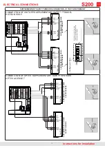
* required only in case of FULL ENERGY mode
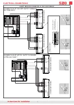
Verify the sensor configuration directly in the manufacturer’s manual
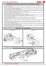
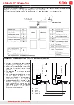
2) TURN THE AUTOMATION 180° AND CONNECT THE LOW ENERGY PLUG
1) DISCONNECT THE FULL ENERGY PLUG
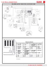
ELECTRONIC BOARD DIP-SWITCHES SETTING
ONLY IN CASE OF LOW ENERGY INSTALLATION WITH ARTICULATED ARM AND DOOR WIDTH BELOW 800mm:
3) REDUCE THE SPRING TENSION
a) Loosen the grub screw in the electronic
board side (GLS) to trigger the anticlockwise
rotation of the spring
b) Screw back GLS
c) Loosen the grub screw in the motor side
GLM) to trigger the anti-clockwise rotation
of the spring
d) Screw back GLM
e) Repeat points a and b
SENSORS POSITION
instructions for installation
PRELIMINARY OPERATIONS
S200
DISCONNECT
CONNECT
open
pushing
open
pulling
full energy
mode-
low energy
mode-
Summary of Contents for S200
Page 20: ...20 instructions for installation LIST OF ERROR MESSAGES AND NOTICES S200 ...
Page 26: ...26 instructions for installation PRE WIRED ELECTRIC CONNECTIONS S200 ...
Page 30: ...30 EC DECLARATION OF CONFORMITY instructions for installation S200 ...


