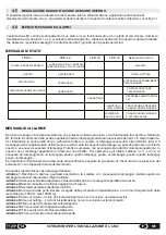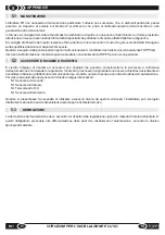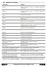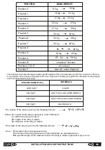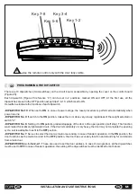
Key 1-2
Key 3-4
Key 5-6
Key 7-8
Use the remote control only with the door fully visible.
-DIP-SWITCH No.10:
When set to
ON
, in case of power outage, the reset procedure is performed automatically when
power returns.
-DIP-SWITCH No. 9:
If switch to the
ON
position, makes the door close very slowly, regardless of the weight selected on
switch "A".
-DIP-SWITCH No. 8:
Setting it to
ON
permits gradual stoppage of the door in the open position (soft stop). This function
was created for relatively lightweight doors; if the door is moderately or very heavy, the door may not complete the opening
cycle, so it is advisable to set it to the
OFF
position.
-DIP-SWITCH No. 7:
Serves to select the door as main or secondary in case of tandem operation. In the
ON
position, the
door functions as the main door and in the
OFF
position, the door has secondary function and stands by for commands
from a main door.
-DIP-SWITCHES no. 6-5-4-3-2-1:
These are used to set the door address. In case of a single door, all the dip-switches
must be set to
OFF
. In case of tandem operation, the setting of the dip-switches must be identical for both doors.
4.4
PROGRAMMING THE DIP-SWITCH
There are 10 dipswitches (microswitches) on the circuit board, accessible by opening the cover on the control board
(Figure 20).
Each dip-switch (Figure 26 reference “C”) can be set in 2 positions, marked ON and OFF. At the first use, all the
dipswitches are set in the OFF position except dips 7-9-10, which is set to ON.
Hereafter we indicate the functions of each dipswitch.
28
INSTALLATION AND USE INSTRUCTIONS
EN
M1
Summary of Contents for M1
Page 2: ...2 ISTRUZIONI PER L INSTALLAZIONE E L USO IT M1 ...
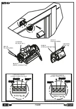
Page 34: ... 34 FIGURE M1 Fig 11 5 0 Fig 10 ...
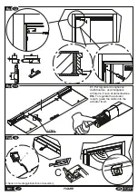
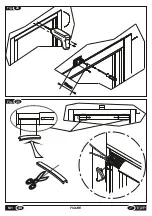
Page 37: ...Fig 19 75 10 Fig 20 37 M1 FIGURE ...
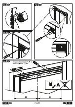
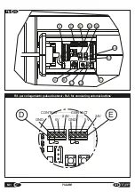
Page 38: ... M1 FIGURE 38 Fig 21 Fig 22 ...
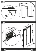
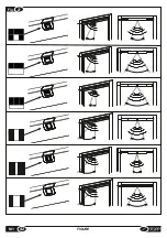
Page 40: ... M1 FIGURE 40 Fig 70mm 24 Fig 25 TOPP M1 TOPP M1 ...
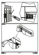
Page 42: ... M1 FIGURE 42 Fig 27 ...

