2.5
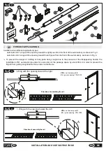
TYPES OF APPLICATIONS
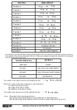
Available in two different application types:
automation for 1 wing with the opening toward the right (seen from the front of the automation), as shown in Fig. 3;
automation for 1 wing with the opening toward the left (seen from the front of the automation), as shown in Fig. 4.
To prevent the danger of clothing or body parts being caught due to the presence of the disappearing handle, the
installation of M1 automation provides for a reduction of the passage space by about 80 mm in order to prevent the
fingers from getting caught inside the sunken counterframe.
22
INSTALLATION AND USE INSTRUCTIONS
EN
M1
Fig.
3
VL
VPA
A
80
A
Direction of assembling the rail
Fig.
4
VPA
VL
A
A
80
Direction of assembly the rail
VPA
= net doorway width
VL
= gross opening 700÷1000
VPA
= net doorway width
VL
= gross opening 700÷1000
1 Wing with the opening toward the right
1 Wing with the opening toward the left
Fig.
2
3
6
4
1
2
7
10
8
9
11
12
13
14
15
5
Summary of Contents for M1
Page 2: ...2 ISTRUZIONI PER L INSTALLAZIONE E L USO IT M1 ...
Page 34: ... 34 FIGURE M1 Fig 11 5 0 Fig 10 ...
Page 37: ...Fig 19 75 10 Fig 20 37 M1 FIGURE ...
Page 38: ... M1 FIGURE 38 Fig 21 Fig 22 ...
Page 40: ... M1 FIGURE 40 Fig 70mm 24 Fig 25 TOPP M1 TOPP M1 ...
Page 42: ... M1 FIGURE 42 Fig 27 ...

