


23
EN
INSTALLATION AND USE INSTRUCTIONS
M1
IT
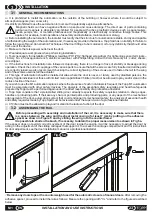
INSTALLATION
3
3.1
GENERAL RECOMMENDATIONS
It is prohibited to install the automation on the outside of the building or however where it would be subject to
atmospheric agents (rain, snow, etc.).
It is strictly prohibited to use the automation in rooms with a potentially explosive atmosphere.
Magnetic fields can have negative effects on people and cause damage. The direct use of parts containing
permanent magnets is absolutely prohibited for people with active prosthetic devices such as pacemakers,
insulin pumps, etc., or metallic prostheses and magnetically or electronically conductive foreign bodies. This
applies, for example, to all operations of assembly and installation, maintenance or storag
Before installing the automation, the installer must verify that the structure for automation is stable, sturdy and capable
of withstanding the weight of the automation and, if necessary provide in that sense. Topp SpA has no liability for failure to
follow the rules of Good Construction Technique of the door fittings to be motorized, or for any deformity that should arise
from use of the device.
Make sure there is a power outlet near the door.
Wear adequate work gloves when performing installation.
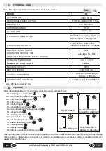
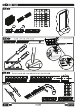
Tools necessary for installation:Phillips screwdriver PH1-PH2; flathead screwdriver (for tightening sensor terminals –
1.6mm); No. 2,5 hexagonal wrench; electric screwdriver with Phillips fitting; drill with 4 mm masonry bit ; cutter; shears;
wire stripper.
If the instructions for installation are followed scrupulously, there is no danger of loss of stability or breakage during
operation. Check the correct couplings of the various parts to ensure that all the screws are fully inserted and all the parts
are correctly joined; we also recommend checking the correct tightening of the screws used to fasten the rail to the wing
and of the screws used install the actuator.
This type of automation should be installed at sites where the door is never, or rarely, used by disabled persons, the
elderly, fragile individuals or those with limited motor capabilities.Children must not be allowed to play and/or stand in the
radius of action of the door.
If you wish to use the M1 automation is places where the presence of such individuals is frequent, the Topp M1 automation
must be associated with other safety devices. The analysis of the essential safety requisites and health safeguards
prepared by Topp must be performed again under the direct responsibility of a professional installer.
Topp SpA considers that a preinstalled sliding door already respects the safety requisites relative to sharp edges,
handles or protruding parts. If their are any sharp or pointed parts and protruding parts, or any aspect of the mechanical
arrangement of the door-automation system that could endanger its mechanical safety, the analysis of essential health
and safety requisites made by Topp SpA must be reviewed under the supervision of a professional installer.
Children must not be allowed to play and/or stand in the radius of action of the door.
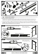
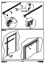
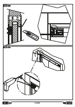
Before proceeding with assembly and installation of the rail, it is necessary to make sure that there
is a space between the wing and the sheet metal casing of at least 7 mm by putting on the adhesive
spacer as shown in Figure 5 and by sliding the wing into the counterframe.
It is possible to shorten the brush, if necessary, to obtain the proper measurement as shown in Fig.5a.
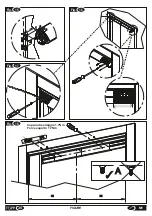
If the spacer does not permit correct movement of the door inside the casing, it will be necessary to adjust the door by
acting on the adjustment of the sliding carriages that support it. To access the carriage compartment and for instructions
for door adjustment, see the door installation manual or a professional installer.
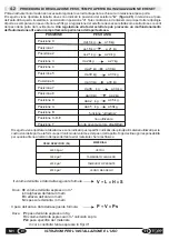
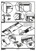
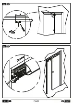
3.2
ASSEMBLING THE RAIL
Remove any doorstops or the counterweight used for the automatic closure of manual doors
.After removing the
adhesive spacer, proceed to install the rail as follows: Measure the opening width "VL" and refer to the figures described
below.
60
Fig.
5a
Fig.
5
Summary of Contents for M1
Page 2: ...2 ISTRUZIONI PER L INSTALLAZIONE E L USO IT M1 ...
Page 34: ... 34 FIGURE M1 Fig 11 5 0 Fig 10 ...
Page 37: ...Fig 19 75 10 Fig 20 37 M1 FIGURE ...
Page 38: ... M1 FIGURE 38 Fig 21 Fig 22 ...
Page 40: ... M1 FIGURE 40 Fig 70mm 24 Fig 25 TOPP M1 TOPP M1 ...
Page 42: ... M1 FIGURE 42 Fig 27 ...


