background image

ZF-A5645-MANUAL 


2, touch screen operation and its function explanation 

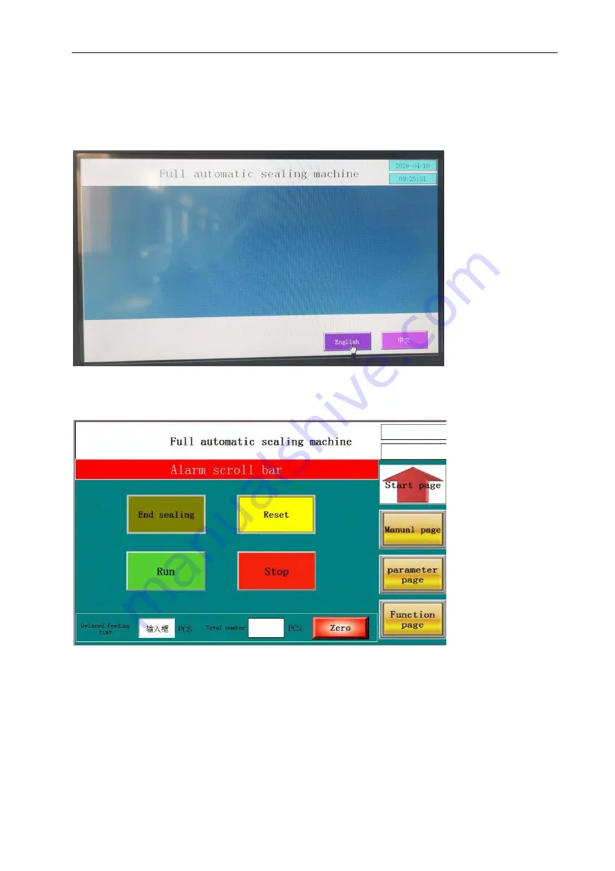
(1) to open the main power switch, touch screen display the home page as shown 


Select the “automatic page” and the submenu appears as shown in Figure 5.3 


A. Run: click the "Run" button, and then the device enters the running state 

B. Stop: click the “stop” button, and the device stops 

C. Reset: when the device alarm, click the "reset" button to clear the alarm and the 

device enters the normal preparation state. 

D. Manual sealing: click it to manual seal 

5.2 

Summary of Contents for ZF-A5645

Page 1: ...ty precautions 2 the safety operation precautions 3 the mechanical specifications 4 the mechanical installation 5 mechanical debugging and operation 6 mechanical adjustment 7 mechanical maintenance 8...

Page 2: ...sures 6 the machine is not suitable for packaging explosives products In addition if you want to package small items or liquid powder should first have them packed in boxes tanks bags and other packag...

Page 3: ...in case the hand was jammed or caught into the machine 3 When the machine automatically run should keep the safety door close to avoid any contact with the sealing device and cause injury by burns an...

Page 4: ...t be replaced by new one so as not to affect the quality of sealing and sealing knife life When there is film on the knife or other debris need to use cotton towel clean the knife When cleaning the em...

Page 5: ...ling Knife Size mm L 565 W 460 Packing Products Size L W H mm 100 450 60 350 5 120 Max Packing Width 23 Production Capacity 30Pcs min Conveyor speed m min 26M min Packing Material POF PE Sealing Knife...

Page 6: ...ZF A5645 MANUAL 1515 750 1 7 9 5 1570 880 400 C C 2 Machine Size Unit mm...

Page 7: ...ZF A5645 MANUAL 3 Operate Panel...

Page 8: ...to the intended location to match the production line 2 mechanical height adjustment use the wrench to loosen the lock nut under the rack and then adjust the height adjustment nut until the required...

Page 9: ...o the operating state 4 Pneumatic device As shown in Figure 4 2 the air pressure throat connected to the machine s air pipe open the intake valve and then rotate the air adjustment device so that the...

Page 10: ...he center control system Set the temperature of heating tube for the side sealing knife to control the sealing performance When select 1 or ON the sealing knife hearing tubes start working will heatin...

Page 11: ...he automatic page and the submenu appears as shown in Figure 5 3 A Run click the Run button and then the device enters the running state B Stop click the stop button and the device stops C Reset when...

Page 12: ...l once B Synchronous film pulling when click pulling film the action of sending film and pulling film goes when release the action stop C Front conveyor click front conveyor and enter manual operation...

Page 13: ...delayed time of pulling Select the function page and the submenu appears as shown in Figure 5 6 A Program switching click it to make switch between hollow products and solid products B Machine close...

Page 14: ...in Figure 5 1 3 shrink film width calculation method shrink film width package width W package high H 4 6 inches 4 tripod and conveyor belt adjustment A Tripod height adjustment Figure 5 2 turn the ha...

Page 15: ...of the Product height 5 Load shrink film to the film fixing roller A As shown in Figure 5 3 the shrink film is placed on the film feed roller Note that the opening side of the shrink film must face t...

Page 16: ...he film should be moved 5mm in the direction of the positioning rod C After adjusting the film position move the positioning rod on both sides adjust it to both ends of the film and then lock the nut...

Page 17: ...rated and the roller device is turned up and then spread through the film as in the diagram of 5 4 then reset the handle and pin roller Depending on the packaging the number of needle pin roller is di...

Page 18: ...or not 11 If the above action is normal press the manual sealing switch once at that time the sealing knife will carry out the sealing action and complete the sealing and cutting of the shrink film 12...

Page 19: ...select set the longer time the longer the length of the pre feeding film B Adjust the extension of the sealing method to extend the length of the seal according to the electric eye pattern If the eye...

Page 20: ...r sealing temperature 15 If the sealing line is satisfied the sealing machine debugging is completed 2 the machine features 1 The machine has a safety protection function and alarm device 2 sealing sy...

Page 21: ...ough the electric eye restore the shot Using this transaction of electrical signal to control the relay B When the packaging items are transparent or of irregular shape especially the objects have hol...

Page 22: ...automatic Select STARTUP D Put the pack product into the conveyor sealing action finish automatically A The machine is equipped with two emergency stop device if any abnormal conditions found press t...

Page 23: ...e source switch 2 shutdown procedures A First turn off the heater so that the electric tube cooling but this time heating tube still with high temperature pay attention to avoid burns select B Then tu...

Page 24: ...htly in contact with the limit switch and the feed motor is not running When the swing arm is in the position as shown in Figure 6 1B The trigger wheel turns through a certain angle and top the limit...

Page 25: ...t conveyor adjustment device 2 When the belt is too loose loosen the screw 1 then turn the screw 2 clockwise push the rolling axle to the right and gently press the belt Fix the screw 1 to the appropr...

Page 26: ...the rolling shaft and the belt Note After adjusting the screws let the machine run for about ten minutes If the conveyor belt is not offset the adjustment is completed 4 4 Rear conveyor belt part the...

Page 27: ...p and down the fixed nut adjust to the average speed then lock the fixed nut if the knife is damaged you need to replace the heat seal knife and then adjust as the above method 6 sealing protection de...

Page 28: ...m to promote the sealing device to carry out the scissor type sealing action The cylinder has a sealing knife to drop the magnetic switch PS2 When the piston of the cylinder reaches the stroke positio...

Page 29: ...guard plate pressure to the packing product and the trigger wheel has triggered an abnormal sealing signal in the product s height trigger principle refer to the above point b and priority to the set...

Page 30: ...gger wheel and the proximity switch the device will lose the role of protection 7 the scrap winding part the removal of waste film scraps 1 Loose and remove the nut firstly and then remove the fixed d...

Page 31: ...d to do the maintenance of the machinery Make sure the power cut off before maintenance to avoid danger 1 the pressure adjustment combination maintenance Pneumatic control valve maintenance When the w...

Page 32: ...the nut 5 chain and sprocket maintenance about once every three months maintenance first remove the shield then apply butter to the chain and sprocket Install the cover after maintenance 6 bearing an...

Page 33: ...ube wires located in the wiring box 3 Loose the fixing screws remove the electric tube and then install the new heating tube 4 lock the fixing screw connect the heating tube line and lock the wiring b...

Page 34: ...the knife from the upper knife holder 3 Loose the screws on the connection block and remove the connection block 4 Remove the heating sub assembly 5 clean the sealing knife if the sealing knife wear a...

Page 35: ...higher Heater switch contact burned out Replace the heater switch TC Temperature controller burned out Replace TC SSR solid state relay burned out Replace SSR Heating tube broken Replace heating tube...

Page 36: ...rap motor Scraps motor broken Replace the scraps motor 9 Sealing device doesn t work PLC 1004 contact damaged Replace contact 1004 or change PLC program or change PLC Sealing solenoid valve broken Rep...

Page 37: ...the product still not completely through the seal seat Increase the time of seal timer Pack product is transparent or has gap Refer to view compensation operation 15 Front conveyor deviation run The f...

Page 38: ...ZF A5645 MANUAL Nine Circuit Diagram...

Page 39: ...ZF A5645 MANUAL Ten The explosion figure 1 Overall part diagram...

Page 40: ...ZF A5645 MANUAL 2 Control electric box components...

Page 41: ...ZF A5645 MANUAL 3 Safe cover components...

Page 42: ...ZF A5645 MANUAL 4 Sealing components...

Page 43: ...ZF A5645 MANUAL 5 Behind conveyor components...

Page 44: ...ZF A5645 MANUAL 6 Frame components...

Page 45: ...ZF A5645 MANUAL 7 Pull film components...

Page 46: ...ZF A5645 MANUAL 8 Recycle feeding components...

Page 47: ...ZF A5645 MANUAL 9 Electric box components...

Page 48: ...ZF A5645 MANUAL 10 Sending feeding components...

Page 49: ...ZF A5645 MANUAL...

Page 50: ...ZF A5645 MANUAL 11 Front conveyor components...

Page 51: ...ZF A5645 MANUAL...

Reviews: