PLS-601 User's Manual
Document #11696 Page - 14
4.0 USING THE PLS-601
It is strongly recommended that this portion of the User’s Manual be read in its entirety before
placing your PLS-601 into operation. Failure to follow the instructions given in the following
sections may void your PLS-601 warranty.
4.1 INSTALLATION
ALL PLS-601 ELECTRICAL CONNECTORS MUST CONFORM TO THE NATIONAL
ELECTRIC CODE AND ANY LOCAL ELECTRIC CODES IN EFFECT.
IN THE CASE OF ANY DISCREPANCIES BETWEEN THE ELECTRIC CODES AND THESE
INSTALLATION INSTRUCTIONS, THE ELECTRIC CODE MUST TAKE PRECEDENT.
4.1.1 MOUNTING THE RESOLVER
The RESOLVER is designed to be mounted on the target machine, and coupled to the target
machine shaft. The RESOLVER should be mounted and coupled in a manner such as to minimize
shock, vibration, as well as axial and radial shaft loading.
The RESOLVER may be mounted via the standard front face mount or the optional foot-type
mounting adapter.
4.1.2 MOUNTING THE CONTROL UNIT
The PLS-601 Control Unit is designed to be mounted in a NEMA type enclosure, which is suitable
for the ambient environment. The enclosure must protect the Control Unit from contamination
caused by water, oil, dust, or corrosive gases. The Control Unit should not be subjected to
excessive amount of mechanical shock or vibration.
The mounting location should be chosen such as to avoid exposure to significant levels of
electromagnetic interference (EMI), which can be induced by devices such as motor starters and
control relays. The operating temperature must be maintained between 32°F and 125°F.
4.1.3 CONNECTING THE RESOLVER TO THE CONTROL UNIT
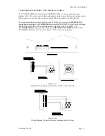
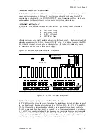
The Resolver is connected to the PLS-601 Control Unit via the Resolver/Control Unit Interface
Cable. The Cable is a 3-pair, individually shielded cable, containing an eight pin female plug-
connector on one end, and a seven pin female MS-type connector on the other.
The standard interface cable is wired at the factory to provide an INCREASING angular position
reading for CLOCKWISE rotation of the Resolver shaft (when looking into the END of the shaft).
An INCREASING angular position reading during COUNTERCLOCKWISE rotation of the
Resolver shaft may be achieved by interchanging two of the wires that are brought into the eight
pin female connector. See SECTION 3.3 for complete wiring details.
The interface cable may be a maximum length of 2500 feet, and should always be routed in such a
manner as to avoid exposure to electromagnetic interference (EMI).


