PLS-601 User's Manual
Document #11696 Page - 8
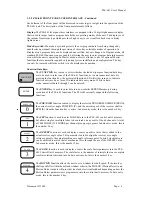
Motion Detect LED:
The MD (motion detect) LED is used to give the status of the MOTION
DETECT output. The MD LED is active whenever the resolver shaft speed value (RPM) falls
within the programmed MOTION DETECT window. The MOTION DETECT output is brought
out to the twenty pin male connector that is located on the bottom of the PLS-601 Control Unit.
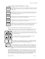
3.2.4 AC/DC POWER SYSTEM
The AC POWER PLUG offers a safe, convenient method of providing AC power to the
CONTROL UNIT - eliminating the need to connect individual power wires. An RFI LINE
FILTER provides built in protection against RFI (Radio Frequency Interference) induced line
noise. An AC POWER FUSE provides electrical protection for the CONTROL UNIT’s
electronics. The internal DC POWER SUPPLY provides DC power for the CONTROL UNIT as
well as up to four solid state relay boards or one electromechanical relay board. This eliminates
the need for an external power supply.
3.2.5 INTERFACE CONNECTORS
Three interface connectors are supplied on the standard PLS-601 CONTROL UNIT: a
TRANSDUCER INTERFACE CONNECTOR, a COMMUNICATIONS OUTPUT
CONNECTOR, and a RELAY OUTPUT BOARD connector. These connectors are located on the
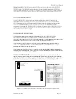
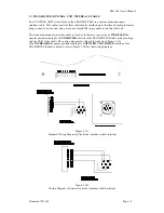
bottom side of the CONTROL UNIT ENCLOSURE, as shown in FIGURE 3.2.5.
The TRANSDUCER INTERFACE CONNECTOR is an eight-pin male connector, used to
interface the CONTROL UNIT to the TRANSDUCER. Refer to SECTION 3.3 for complete
details on the TRANSDUCER INTERFACE.
The COMMUNICATIONS OUTPUT CONNECTOR is a four-pin male connector that provides
serial data to the remote display. If the CONTROL UNIT is configured for RS232 output, the data
can interface to an external computer or PLC.
The RELAY OUTPUT BOARD connector is a twenty pin male connector used to interface to
either a solid state relay board or an electromechanical relay board. The pin-out of this connector
will not be detailed because of the proprietary interface between the PLS-601 and the relay output
boards. The remaining connectors and their pin-out definitions are defined in Figure 3.2.5.
Figure 3.2.5 Bottom view of PLS-601 control unit and connector pin-out definitions.
Communications Connector
Pin 1
Ground
Pin 2
RD
Pin 3
TD
Pin 4
CTL1
Resolver Interface Connector
Pin 1
No connection
Pin2
No connection
Pin 3
S1 (Stator 1)
Pin 4
S3 (Stator 3)
Pin 5
S4 (Stator 4)
Pin 6
S2 (Stator 2)
Pin 7
R2 (Rotor 2)
Pin 8
R1 (Rotor 1)


