PLS-601 User's Manual
Document #11696 Page - 10
3.4 PLS-601 RELAY OUTPUT BOARDS
The PLS-601 is available with solid state or electromechanical relay boards. Each relay board can
contain up to seventeen relays. Sixteen of these relays are dedicated for channel outputs. The
remaining relay is dedicated to the MOTION DETECT output. A maximum of four relay boards
can be interfaced to the control unit, providing a total of sixty-four relay outputs.
3.4.1 Solid State Relay Board
The solid state relay board is available with four different types of relays. These relays are as
follows:
•
120 VAC at 3 Amps
•
240 VAC at 3 Amps
•
60 VDC at 3 Amps
•
200 VDC at 1 Amp
All solid state relays are optically isolated and individually fused for safe, reliable operation. Each
relay also has an associated LED to indicate its ON/OFF status. An additional feature of the PLS-
601, is that the internal power supply can drive up to four fully loaded solid state relay boards.
This eliminates the need for an external power supply.
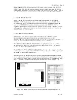
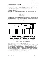
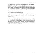
Figure 3.4.1 shows the layout of the solid state relay board.
+
MD
-
+ - + - + - + -
+ - + - + - + -
+ - + - + - + -
+ - + - + - + -
1
2
3
4
5
6
7
8
9
10
11
12
13
14
15
16
ENA
1
2
3
4
5
1
2
3
4
5
P102
P101
6
1
MD
2
3
4
5
9
7
8
10
11
12
13
16
14
15
A
B
C
D
I
N
P
U
T
D
H
C
H
B
H
A
H
D
L
C
L
B
L
A
L
P100A
P100B
16 ERR
INT EXT
ENABLE
1
Channel Group Jumpers
2
Interface Connectors
Relay 16 Jumper
4
Relay Output Connectors
3
1 2 3
2
1
3
5
Output Enable
Connector
Figure 3.4.1 PLS-601 Solid State Relay Board
(1) Channel Group Jumper Options - Solid State Relay Board
The PLS-601 control unit provides sixty-four channel outputs that are divided into four groups of
sixteen channels each. The channels are designated as A01-A16, B01 - B16, C01 - C16, and D01-
D16. Up to four solid state relay boards, each with sixteen output relays can be attached to the
PLS-601 control unit. Each board must be assigned to one of four output groups designated as A,
B, C, or D. This is done by installing the two channel group jumpers in the proper positions on the
relay board (see "Channel Group Jumpers" in Figure 3.4.1). The solid state relay board must be
configured to match the PLS-601 output group that will drive it. Output Group A will drive relay
output board A, Group B will drive relay output board B and so forth.


