PLS-601 User's Manual
Document #11696 Page - 11
3.4 PLS-601 RELAY OUTPUT BOARDS
- Solid State Relay Board Continued
(2 Interface Connectors) - Solid State Relay Board
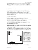
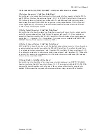
Each solid state relay output board contains two 20 pin male interface connectors labeled P101A
and P101B (see Interface Connectors in Figure 3.4.1). The PLS-601 Control Unit will connect to
P101A through the use of a twenty pin ribbon cable. To add additional solid state relay output
boards, simply connect P101B of the first (or previous) relay output board to P101A of the next
relay output board. Up to four solid state relay output boards can be connected to the PLS-601
Control Unit by this interface method.
(3) Relay Output Connectors - Solid State Relay Board
Each solid state relay board contains four 8 pin plug connectors that provides two output pins for
each of the sixteen channels (see Relay Output Connectors in Figure 3.4.1). These outputs are
normally off until activated by the PLS-601 Control Unit. The solid state relay output connectors
are labeled (+ 1 -) through (+ 16 -). In addition, a 2 pin connector is available for the MOTION
DETECT function. This connector is labeled (+ MD -).
(4) Relay 16 Jumper Options - Solid State Relay Board
Solid state Relay 16 may be used as one of the standard channel output relays, or it may be used as
an indication that an error has occurred in the PLS-601 Control Unit. To enable solid state Relay
16 as a standard output, connect pins 1 and 2 together of J1 (see Relay 16 Jumper in Figure 3.4.1).
To enable solid state relay 16 as an error indicator, connect pins 2 and 3 together of J1. When solid
state relay 16 is used as an error indicator, it will be active in non error conditions (ON) and non-
active in an error condition (OFF).
(5) Output Enable - Solid State Relay Board
Each solid state relay board has a 2 pin input connector that implements an OUPTUT ENABLE
function (see Output Enable Connector in Figure 3.4.1). This connector is labeled ENA. The ENA
pins must be shorted together in order for any of the seventeen solid state relay outputs to be
enabled. If this connection is opened, all seventeen solid state relay outputs will be disabled.


