Portable Optical Tweezers Kit
Chapter 5: Setup and Adjustment
Page 62
MTN024417-D02
Step 6: Final Corrections and Potential Errors
•
If you still have trouble seeing the laser spot, set the red amplification to maximum
when adjusting the live image. You can also try dimming the LED.
•
If trapping is weak, slightly move the sample up or down to find the optimal plane
of trapping.
•
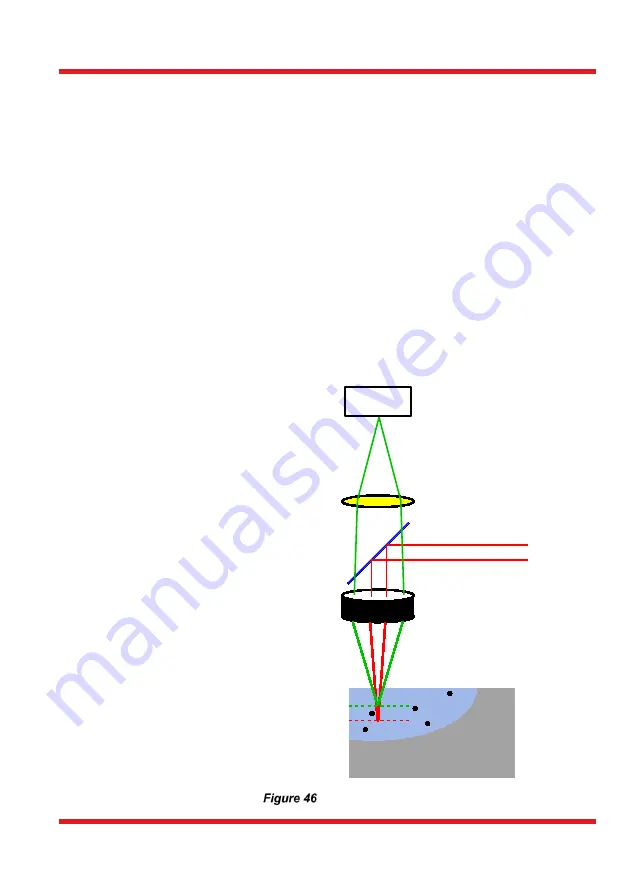
If the laser spot is in a significantly different plane than the plane where the beads
can be seen sharply, you may have to adjust the focal planes, see Figure 46 and
the explanation below. Move the lens in front of the camera in the Z direction
along the cage rods until you have a sharp image of both the beads and the laser
spot. If beads are pulled out of the focal plane when trapped, the focal planes do
not coincide.
•
If you want the movement in Z direction to be smoother, a hex key can be inserted
in the adjuster of the MT1B. This allows you to move the stage up and down with
less vibration in the system.
Laser Focal Plane vs. Microscope Focal Plane
The position of the laser
focus in the Z direction
is defined by the focal
length of the objective
(red curve in Figure 46).
For ideal observation of
both the laser focus and
the trapped sample
beads it is necessary to
adjust the microscope
(tube) lens (shown in
Figure 46) in such a way
that the focal plane of
the observing camera
system (green curve) -
consisting
of
the
objective, the tube lens
and the CCD camera
chip - coincides with the
fixed focal plane of the
laser. When adjusted
correctly, the focused
laser spot, as well as the
sample beads in the
plane of the focus, are
both visible through the
microscope.
Laser and Camera Focal Planes
Camera
Microscope Lens
Beamsplitter
Laser
Objective
Focal Plane Camera
Focal Plane Laser
Summary of Contents for EDU-OT3
Page 1: ...EDU OT3 EDU OT3 M Portable Optical Tweezers User Guide...
Page 93: ......
Page 94: ...www thorlabs com...


