Portable Optical Tweezers Kit
Chapter 5: Setup and Adjustment
Page 38
MTN024417-D02
Microscope Assembly
•
Attach the LED assembly to the damped post.
The LED can be in contact with the breadboard.
Try to align the cage plate of the LED assembly
parallel to the breadboard hole pattern.
•
Attach the objective assembly to the damped
post. The distance from breadboard top to the
bottom of the objective should be about
11.5 cm.
Use a level at the beamsplitter cube to make
sure the assembly is vertical
. If not, you have
to adjust the angle in which the C1498(/M)
clamp is screwed to the cage plate.
•
Put the camera assembly on top of the
objective assembly. The short cage rods on top
of the beamsplitter should fit easily into the thick
cage plate at the bottom of the camera
assembly. If not, adjust the angle at which the
C1498(/M) clamp is screwed to the respective
cage plate.
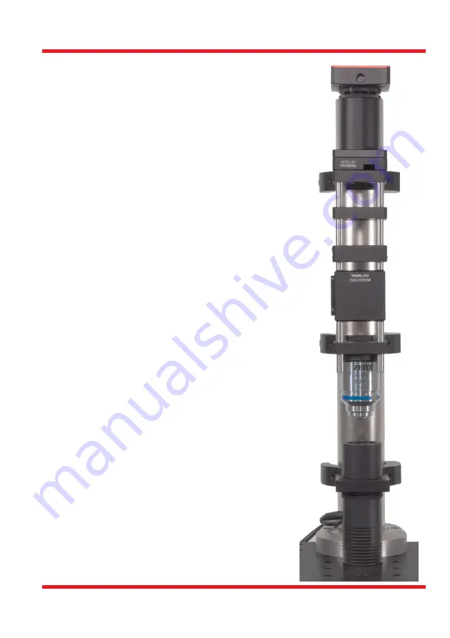
The microscope assembly is now complete and should
look like the image on the right.
Summary of Contents for EDU-OT3
Page 1: ...EDU OT3 EDU OT3 M Portable Optical Tweezers User Guide...
Page 93: ......
Page 94: ...www thorlabs com...


