Revision
B.000
Service
Manual,
Partisol
Model
2000
Air
Sampler
S
ECTION
2
: T
ROUBLESHOOTING
G
UIDES
P
AGE
2-8
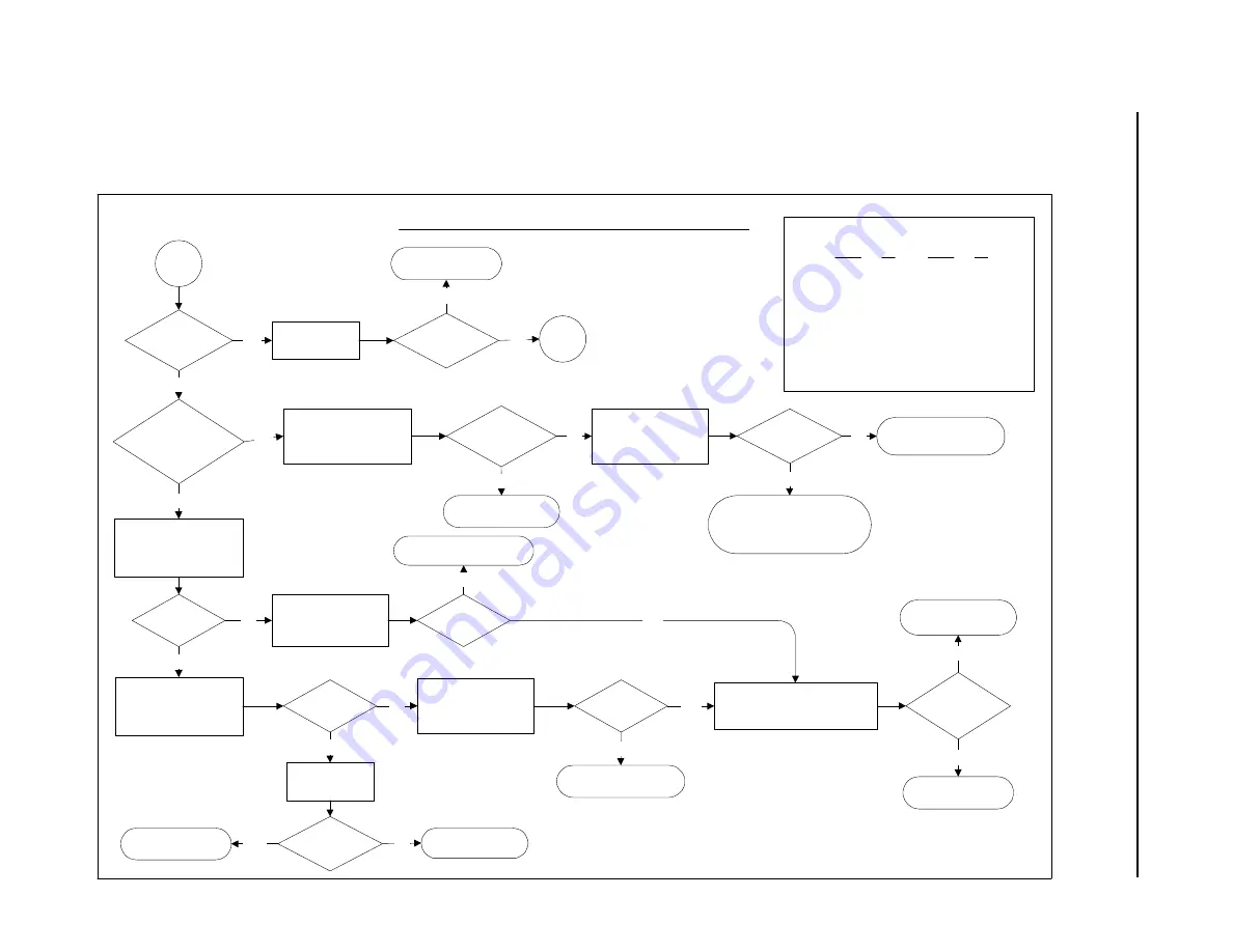
DISPLAY TROUBLESHOOTING FLOW CHART-B
B
Note:
1.Pins for continuity check of cable P16A to P1:
P16A
P1
P16A
P1
Pin 1
Pin 1
Pin 12
Pin 12
Pin 2
Pin 2
Pin 13
Pin 13
Pin 3
Pin 3
Pin 14
Pin 14
Pin 5
Pin 5
Pin 15
Pin 15
Pin 6
Pin 6
Pin 16
Pin 16
Pin 7
Pin 7
Pin 17
Pin 17
Pin 8
Pin 8
Pin 18
Pin 18
Pin 9
Pin 9
Pin 19
Pin 19
Pin 10
Pin 1
Pin 20
Pin 20
Pin 11
Pin 11
Yes
No
Is pump still
running?
Yes
No
Is
electronics
compartment
temperature
> 2°C?
Place multimeter across
test point +24V (red) and
PGND (black) on interface
board.
Voltage =~
24V?
No
Yes
Perform system
reset.
Resume normal
operation.
Problem
corrected?
No
Yes
Place multimeter across
test point +6V (red) and
PGND (black) on interface
board.
Voltage =~ 6V?
Yes
No
Check the 4A fuse used
for the [email protected]
voltage from
transformer
Fuse OK?
No
Check the 5A fuse used
for the [email protected]
voltage from
transformer.
Fuse OK?
No
Yes
Original boards were
defective.
Replace interface/CPU board
assembly with known good one
R&P P/N 50-005496 & 10-002407
Problem
corrected?
No
Yes
Replace transformer
R&P P/N 03-002402
Place hand near (do NOT
touch!) the heater at the
top of the electronics
compartment.
Yes
No
Heat coming
from heater?
Wait for instrument to
warm up.
Perform system
reset.
Resume normal
operation.
Problem
corrected?
No
Yes
Contact R&P.
Check continuity
between the heater
terminals and P11 on
the interface board.
Continuity OK?
No
Yes
Replace heater
R&P P/N 56-005909-0120
or 56-005909-0240
Replace fuse
R&P P/N 04-005510-0004
Replace fuse
R&P P/N 04-003681
Yes
Go to A
Replace interface/CPU
board assembly
R&P P/N 50-005496
& 10-002407
Summary of Contents for PARTISOL 2000
Page 2: ......
Page 8: ...This page left intentionally blank...
Page 28: ...This page left intentionally blank...
Page 62: ...This page left intentionally blank...
Page 80: ...This page left intentionally blank...


