14
F. LIMIT POSITION AND LOCATION
WARNING:
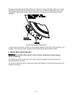
The predetermined limit locations on all of the THV1M119A* oil-fired furnaces have been
tested and approved. Any attempt to relocate these safety controls or replace these safety controls with a
control that is not approved, or is incompatible, may result in personal injury, substantial property damage
or death.
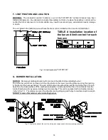
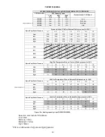
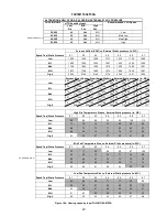
The unit listed in the table below must have the limit control installed at the time of unit installation.
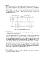
Fig. 10: Limit location for
THV1M119A*
G. BURNER INSTALLATION:
NOTICE:
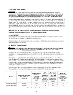
Remove all cardboard packing from around chamber before installing burner.
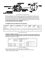
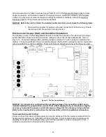
The oil burner will mount on three stud mounting bolts on the lower mounting plate covering the opening
in the front of the heat exchanger. The end of the burner tube should be inserted no further than 1/4 inch
back from the inside surface of the combustion chamber. A distance further than 1/4 inch back from the
inside chamber wall may cause impingement and sooting. This unit is equipped with a chamber retainer
(refer to Fig.11). The retainer secures the chamber during shipping and helps to maintain insertion depth.
DO NOT remove this retainer when installing burner.
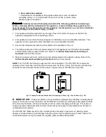
Fig. 11: Typical location of the over fire air tap and components in burner mounting plate area
TABLE 4: Installation location of
the fan and limit control for each
furnace
Summary of Contents for THV1M119A960SA
Page 2: ......
Page 4: ......
Page 6: ...2...
Page 36: ...32 V Sequence of Operations Flow Chart...
Page 37: ...33...
Page 38: ...34 VI Trouble Shooting Flow Chart...
Page 39: ...35...
Page 40: ...36...
Page 41: ...37...
Page 42: ...38...
Page 44: ...40 Appendix A Replacement Parts for THV1M119A...
Page 45: ...41...
Page 46: ...42 Appendix B THV1M119A960SA PSC Wiring Diagram...


