15
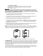
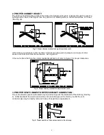
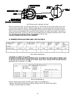
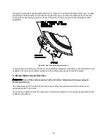
Fig. 12: Burner insertion illustration (Top view)
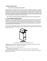
When mounting the burner, the mounting plate (Fig. 11) must be removed to provide access to the area
in front of the combustion chamber. A fiber insulating sleeve or amulet is provided on the burner tube of
specific burners.(see Fig. 12). See burner application chart for type of insulator. Do not allow the burner
tube or end cone to physically touch or protrude into the chamber, as excess heat transfer could result in
destruction of the tube, end cone or both. The burner tube/end cone is properly positioned, when the end
is ¼ inch back from the inside surface of the combustion chamber wall.
DO NOT CHANGE POSITION OF THE CHAMBER!
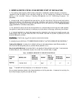
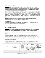
H. BURNER SPECIFICATIONS AND APPLICATIONS:
FURNACE MODEL
THV1M119A*
BURNER
BURNER
SPEC
NO.
*
INS
BURNER MODEL
& TUBE LENGTH
HEAD
STATIC
PLATE
MAXIMUM
NOZZLE
SIZE**
SHIPPED
NOZZLE
SIZE
OIL
PUMP
PRESSURE
(PSIG)
BECKETT (AFG)
TP2701
N
AFG-4.5”
F6
2-3/4U
1.10X80° A
1.00X80° A
120
Table 5: Burner specifications
* INSULATOR S = SLEEVE OR N = NONE
THE NOZZLE SIZE GIVES THE NOMINAL FLOWRATE, IN GPH, FOLLOWED BY THE SPRAY ANGLE, IN DEGREE’S, AND
THE SPRAY PATTERN, EITHER “A” FOR HOLLOW CONE OR “B” FOR SOLID CONE. FOR EXAMPLE, A NOZZLE RATED
AT 0.65 GPH @ 100 PSIG THAT PROVIDES AN 80° SPRAY ANGLE AND A HOLLOW SPRAY PATTERN WOULD BE
ABBREVIATED IN THE TABLE AS “0.65 X 80
A”.
INPUT CAPACITY SELECTION CHART
UNITS
EQUIVALENT
HEAT INPUT
RATE* (BTU/HR)
EFFECTIVE
HEATING
CAPACITY**
(BTU/HR)
NOZZLE SIZE (GPH x TYPE)
Beckett AFG
THV1M119A*
119,000
101,000
0.85 x 80° A
THV1M119A*
140,000
119,000
1.00 x 80° A
THV1M119A*
156,250
132,000
1.10 x 80° A
Table 6: Oil nozzle capacity
All rates shown achieved with 120 PSIG pump pressure for Beckett AFG.
* Based on #2 domestic heating fuel oil having heating value of 140,000 BTU per gallon.
** Based on thermal efficiency of 85.8%.
Summary of Contents for THV1M119A960SA
Page 2: ......
Page 4: ......
Page 6: ...2...
Page 36: ...32 V Sequence of Operations Flow Chart...
Page 37: ...33...
Page 38: ...34 VI Trouble Shooting Flow Chart...
Page 39: ...35...
Page 40: ...36...
Page 41: ...37...
Page 42: ...38...
Page 44: ...40 Appendix A Replacement Parts for THV1M119A...
Page 45: ...41...
Page 46: ...42 Appendix B THV1M119A960SA PSC Wiring Diagram...

