


4
b.
Non-combustible material:
“...material that is not capable of being ignited and burned; such as material
consisting entirely of, or a combination of, steel, iron, brick, concrete, slate,
asbestos, glass, and plaster.”
:
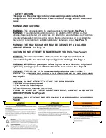
Carefully read and thoroughly understand the following guidelines and warnings
before continuing with the installation of this appliance. Failure to follow these guidelines can
cause improper and unsafe operation of this appliance. Unsafe operation can result in substantial
property damage, severe personal injury, or death.
1. This appliance shall be used with only the type of fuel oil for which it is approved. Refer to the
appliance-rating label for the required type of fuel.
2. This appliance is an oil-fired furnace designed for installation on non-combustible materials. This
appliance is also approved for attic installation on non-combustible materials.
3. Ensure that adequate combustion and ventilation air is available to the unit.
4. The airflow resistance of the duct system attached to this appliance must fall within the allowable
external static pressure range for this unit. Refer to the
Airflow Requirements and Sizing of
Ductwork
section of this manual.
5. Make sure supply and return air ducts are completely sealed to the appliance casing. Refer to the
Airflow Requirements and Sizing of Ductwork
section of this manual.
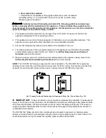
NOTE:
The THV1M119A* furnace is approved for closet installation. The THV1M119A* requires two
openings in the closet door, each having a minimum area of 181 sq. inches. This free area intentionally
exceeds the recommended minimum free area of 1 square inch per 1000 BTUH of input rate.
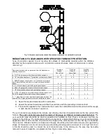
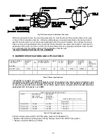
Fig 1: Properly Positioned Combustion Air Openings In Walls (Fig. 1A) and Doors (Fig. 1B).
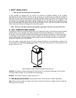
B. MAKE-UP AIR:
Today's emphasis on home insulation increases the probability of inadequate air
supply to the furnace. Heavy insulation cuts off infiltration of outside air, which previously replaced inside
air removed by bathroom, kitchen and laundry vent fans, and air escaping up chimneys. This causes a
negative pressure differential within the home that reduces the supply of air available to the furnace for
combustion and ventilation.
The THV1M119A* Make-Up-Air Control, installs quickly and easily on any warm air heating system,
delivers controlled, fresh air automatically during the winter and a constant supply of clean, fresh air for
comfortable summer living. It resolves the negative pressure differential problem.
Summary of Contents for THV1M119A960SA
Page 2: ......
Page 4: ......
Page 6: ...2...
Page 36: ...32 V Sequence of Operations Flow Chart...
Page 37: ...33...
Page 38: ...34 VI Trouble Shooting Flow Chart...
Page 39: ...35...
Page 40: ...36...
Page 41: ...37...
Page 42: ...38...
Page 44: ...40 Appendix A Replacement Parts for THV1M119A...
Page 45: ...41...
Page 46: ...42 Appendix B THV1M119A960SA PSC Wiring Diagram...