


26
N. STARTUP PROCEDURES:
A. Heating System
1. Initial Startup:
: Turn off power to furnace. Before the oil piping system is placed into service, it must
have been leak tested by a qualified heating contractor.
: For initial start-up of the appliance after installation, it may be necessary to purge the
air out of the oil line. A qualified heating contractor should do this.
Operating Instructions:
i.
STOP! Read the safety information above.
ii.
Set the thermostat to the lowest setting.
iii.
Turn off all electric power to the appliance.
iv.
This appliance is equipped with an ignition system that automatically lights the
burner. Do not try to light the burner by hand.
v.
Rotate the manual oil shutoff valve to the “ON” position.
vi.
Turn on the electric power to the appliance.
vii.
Set the thermostat to the desired setting.
viii.
If the appliance will not operate, call your qualified service technician or oil supplier.
To Turn Off Oil to Appliance:
i.
Set the thermostat to the lowest setting and set the operating mode switch to “OFF”.
ii.
If service is to be performed, turn off the electrical power to the appliance.
iii.
Turn the manual oil shutoff valve to the “OFF” position.
2. Adjustment of Burner Combustion:
: Maximum gross stack temperature must not exceed 550°F (288°C) under any
circumstances.
: Do not run the oil pump dry for more than five minutes, as irreparable damage may
result.
For Your Safety Read Before Operating:
: If you do not follow these instructions exactly, a fire or
explosion may result causing property damage, personal injury or loss of life.
This appliance does not have a pilot light. It is equipped with an ignition system that
automatically lights the burner. Do not attempt to light the burner by hand.
Do not use this appliance if any part has been under water. Immediately call a qualified
service technician to inspect the appliance and to replace any part of the control system
and any oil control that has been under water.
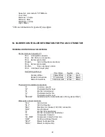
Summary of Contents for THV1M119A960SA
Page 2: ......
Page 4: ......
Page 6: ...2...
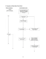
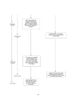
Page 36: ...32 V Sequence of Operations Flow Chart...
Page 37: ...33...
Page 38: ...34 VI Trouble Shooting Flow Chart...
Page 39: ...35...
Page 40: ...36...
Page 41: ...37...
Page 42: ...38...
Page 44: ...40 Appendix A Replacement Parts for THV1M119A...
Page 45: ...41...
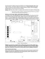
Page 46: ...42 Appendix B THV1M119A960SA PSC Wiring Diagram...