


20
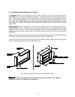
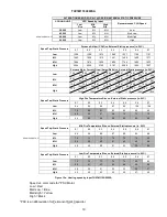
THV1M119A9T5SA
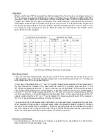
Figure 15b: Heating speed by input
THV1M119A9T5SA
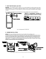
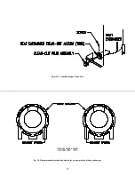
ALTERATIONS REQ’D FOR A/C @ DESIGN EXTERNAL STATIC PRESSURE
COOLING UNIT
HTG Speed by Input
Low Mid High
Fire Fire Fire
Recommended CLG Speed
36,000
ML
Med
MH
Low
42,000
ML
Med
MH
Med Low
AS SHIPPED CLG.
48,000
ML
Med
MH
Med High
60,000
ML
Med
MH
High
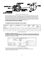
Speed Tap\ Static Pressure
Furnace Airflow (CFM) vs. External Static pressure (in. WC.)
0.1
0.2
0.3
0.4
0.5
0.6
0.7
Low
1520
1429
1385
1311
1222
1139
1085
ML
1660
1593
1536
1491
1422
1369
1295
Med
1749
1693
1652
1572
1520
1465
1391
MH
1827
1766
1692
1674
1596
1540
1487
High
2253
2185
2142
2114
2045
1991
1955
Furnace Motor Current Draw (Amps/Watts) vs. External Static pressure (in. WC.)
Low
2.62
211
2.81
228
2.92
237
3.07
253
3.22
268
3.35
279
3.46
289
ML
3.34
279
3.55
294
3.72
310
3.84
325
4.02
339
4.13
350
4.31
364
Med
3.74
314
3.91
327
4.11
345
4.25
360
4.39
374
4.60
390
4.74
406
MH
4.21
356
4.40
373
4.57
390
4.73
407
4.90
422
501
432
5.12
450
High
7.2
638
7.2
650
7.43
665
7.68
688
7.92
712
8.16
714
8.29
751
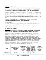
Speed Tap\ Static Pressure
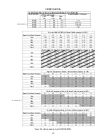
High Fire Temperature Rise vs. External Static pressure (in. WC.)
0.1
0.2
0.3
0.4
0.5
0.6
0.7
Low
80
85
88
93
99
105
112
ML
73
76
79
81
85
89
94
Med
69
72
73
77
80
83
87
MH
66
69
72
72
76
79
82
High
54
56
57
57
59
61
62
Speed Tap\ Static Pressure
Mid Fire Temperature Rise vs. External Static pressure (in. WC.)
0.1
0.2
0.3
0.4
0.5
0.6
0.7
Low
72
77
80
84
90
97
102
ML
66
69
72
74
77
80
85
AS SHIPPED HTG.
Med
63
65
67
70
73
75
79
MH
60
62
65
66
69
72
74
High
49
50
51
52
54
55
56
Speed Tap\ Static Pressure
Low Fire Temperature Rise vs. External Static pressure (in. WC.)
0.1
0.2
0.3
0.4
0.5
0.6
0.7
Low
62
66
68
71
77
82
86
ML
56
59
61
63
66
68
72
Med
54
55
57
60
62
64
67
MH
51
53
55
56
59
61
63
High
42
43
44
44
46
47
48
Summary of Contents for THV1M119A960SA
Page 2: ......
Page 4: ......
Page 6: ...2...
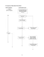
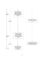
Page 36: ...32 V Sequence of Operations Flow Chart...
Page 37: ...33...
Page 38: ...34 VI Trouble Shooting Flow Chart...
Page 39: ...35...
Page 40: ...36...
Page 41: ...37...
Page 42: ...38...
Page 44: ...40 Appendix A Replacement Parts for THV1M119A...
Page 45: ...41...
Page 46: ...42 Appendix B THV1M119A960SA PSC Wiring Diagram...


