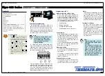


Tiger 320 Series Programming Code Sheet
Draft Copy. Code Version V3.08a
Texmate Inc. Tel. (760) 598 9899 • www.texmate.com
8
2 February, 2005 Prog. Code Sheet V3.08a (NZ101)
CODES 3 to 5
FIRST DIGIT
SECOND DIGIT
THIRD DIGIT
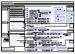
CHANNEL 1 POST PROCESSING
0 Direct Display of Input (no pro-
cessing)
1 Square Root of Channel 1
2 Inverse of Channel 1
3 –
32-POINT LINEARIZATION FOR CHANNEL 1
0 No Linearization on CH1
1 32-point Linearization on CH1 using Table 1
2 32-point Linearization on CH1 using Table 2.
See Note 5
3 32-point Linearization on CH1 using Table 3.
See Note 5
4 32-point Linearization on CH1 using Table 4.
See Note 5
5 125-point Linearization on CH1 (Tables 1 to 4
cascaded).
See Note 5
6 32-point Linearization on CH1 (Tables 1 to 4
selected from the rear pins of selected input
modules).
The selected table is not available if CH2, CH3,
or CH4 is operating in the analog output mode.
CH1 must be set to Voltage, Current in Code 2
[X0X].
See Note 5
7 -
Note:
All linearization tables are set up in the
Calibration Mode [24X].
SERIAL MODE
0 ASCII Mode
1 Modbus Mode
2 Macro master mode (used to cus-
tomize print mode protocols via
macro)
3 Print Mode
4 Ethernet Mode.
See Note 6
5 Devicenet Mode (requires
Devicenet hardware module).
See Note 6
CODE 3 – CHANNEL 1 FUNCTIONS (POST PROCESSING & SERIAL MODE)
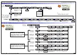
MEASUREMENT TASK
0 Voltage, Current
1 TC (type as per 2nd digit)
2 RTD/Resistance
(type as per 2nd digit)
3 Second Digital Input Channel
(type as per 2nd digit)
FOR VOLTAGE & CURRENT
0 Channel 2 Disabled
1 Direct (no post processing)
2 Square Root of Channel 2
3 Inverse of Channel 2
4 Output Register 1 (smart module)*
5 Output Register 2 (smart module)*
6 Output Register 3 (smart module)*
7 Output Register 4 (smart module)*
32-POINT LINEARIZATION FOR CH2
0 No user defined Linearization
on CH2
1 32-point Linearization on CH2
using Table 1
2 32-point Linearization on CH2
using Table 2.
See Note 5
3 32-point Linearization on CH2
using Table 3.
See Note 5
4 32-point Linearization on CH2
using Table 4.
See Note 5
5 125-point Linearization on CH2
(Tables 1 to 4 cascaded).
See
Note 5
6 –
7 –
CODE 4 – CHANNEL 2 MEASUREMENT TASK AND 32-POINT LINEARIZATION
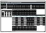
FOR THERMOCOUPLE
0 Type J
1 Type K
2 Type R
3 Type S
4 Type T
5 Type B
6 Type N
7 For sensor tables other than those list-
ed above contact Texmate
FOR RTD TYPE (3-WIRE)
0 Resistance
1 Pt 385 100
Ω
RTD
2 Pt 392 100
Ω
RTD
3 Zn 120
Ω
RTD
4 Cu 10
Ω
RTD
DIGITAL INPUT
0 Frequency - 99.999 Hz range from
0.001 Hz
1 Frequency - 999.99 Hz range from 0.01 Hz
2 Frequency - 99.999 kHz range from 1 Hz
(1 s gate)
3 Frequency - 500 kHz range from 10 Hz
(0.1 s gate)
4 Period - 9.9999 s (100 µs resolution)
5 Period - 999.99 ms (10 µs resolution)
6 Up/Down Counter with Prescaler
7 Set Prescaler
FOR THERMOCOUPLE
0 Type J
1 Type K
2 Type R
3 Type S
4 Type T
5 Type B
6 Type N
7 For sensor tables other than those
listed above contact Texmate
FOR RTD TYPE (2-, 3-, 4- WIRE)
0 Resistance
1 Pt 385 100
Ω
RTD
2 Pt 392 100
Ω
RTD
3 Zn 120
Ω
RTD
4 Cu 10
Ω
RTD
MEASUREMENT TASK
0 No Function
1 Voltage, current
2 TC (3rd digit selects type of TC)
3 RTD/Resistance (3rd digit selects type of RTD)
4 Real Time Clock & Timer (3rd digit selects type)
5 -
6 -
7 Smart Input Module (3rd digit selects register)
CODE 5 – CHANNEL 3 FUNCTIONS
FIRST DIGIT
SECOND DIGIT
THIRD DIGIT
CH3 POST PROCESSING
0 Direct Display of Input
(no processing)
1 Square Root of
Channel 3
2 Inverse of Channel 3
3
4 kilobits Meters
NO Linearization
32 kilobits Meters
32-point Linearization
of CH3 using Table 3
Note:
All linearization
tables are set up in
the Calibration Mode
[24X].
FOR REAL-TIME CLOCK & TIMER
0 HRS:MIN:SEC
1 HRS:MIN
2 -
3 -
4 1 Second Count UP Timer
5 1 Second Count DOWN Timer
6 -
7 -
FOR SMART INPUT MODULE
0 Output Register 1
1 Output Register 2
2 Output Register 3
3 Output Register 4
4 Output Register 5
5 Output Register 6
6 Output Register 7
7 Smart Input Module
Register 2
Code Setup
Note 6:
These functions are not available
on all models and in some cases
require additional hardware.
Note 5:
If only 4 kilobits of memory is
installed, only Table 1 is available for:
•
CH1 in Code 3, 2nd digit.
•
CH2 in Code 4, 3rd digit.
•
CH3 in Code 5, 1st digit.
•
CH4 in Code 6, 1st digit.
•
RESULT in Code 7, 2nd digit.
Note:
The function of the out-
put register selected
varies according to the
input module installed.
*Note:
Selecting 040 to 070 in the 2nd digit of Code 4 selects
one of the following settings in the installed smart input
module’s output register map:
4 selects
5 selects
6 selects
7 selects
Note:
The register map is different for each smart input
module. See installed input module data sheet for
specific smart register 1 function map.
2nd Digit
Input module’s output register map
0
1
2
3
1 =
0.1 second
10 =
1 second
600 =
1 minute
3600 =
1 Hour***
X61 Selects Prescaler
Use
buttons to set
prescale values
***Note:
For the 1 hour setting, the
scale factor for CH1 must be
set to 0.1 in the calibration
mode setting [111].
P
Press
Use the
buttons to set the
required smart input module code
(0 to 377). See installed Input
Module data sheet for code details.


