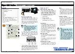


Tiger 320 Series Programming Code Sheet
Draft Copy. Code Version V3.08a
Texmate Inc. Tel. (760) 598 9899 • www.texmate.com
11
2 February, 2005 Prog. Code Sheet V3.08a (NZ101)
Follow These Steps
The following procedures are written for SP1, all other setpoints are con-
figured in a similar manner.
1) Press the
and
buttons at the same time. This enters the set-
point programming mode.The display toggles between [SP_1] and
[18000].
This is SP1 of the
Setpoint Activation Values Mode
. Use the
and
buttons to set SP1 or the
button to move to the required
setpoint.
2) After all required setpoint
activation values
have been set, press
the
button until [SPC_1] appears. This is the
Setpoint & Relay
Control Settings Mode
.
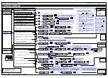
SPC_1 is the
setpoint and relay control settings
programming
menu for SP1. Set the three digits according to the codes in the
Setpoint and Relay Control Function Settings
opposite in the fol-
lowing order:
Third Digit – Setpoint Delay Mode
Set to [XX5] and program the hysteresis, deviation, or PID
functions as required for SP1.
Reset back to [XX0].
Third Digit – Setpoint Timer Mode
Set to [XX6] and program the timer mode functions as
required for SP1.
Reset back to [XX0].
Third Digit – Setpoint Reset & Trigger Functions
Set to [XX7] and program the reset and trigger functions as
required for SP1.
Reset back to [XX0].
Second Digit – Setpoint Activation Source Mode
Set to [X1X] to select the setpoint activation source for SP1
from any channel or selected register shown above. Reset
back to [X0X].
If the SP source is from an external digital input, set to one of
either [X2X] to [X7X] to select the setpoint activation source
from one of six digital inputs (2 to 7).
See *Note at 2nd digit.
First Digit – Relay Energize Mode
Select the relay energize mode for SP1 from 0 to 3.
Third Digit – Relay Latching & Manual Reset Functions
Program the third digit setpoint relay latching and manual
reset functions between 0 to 4 as required.
3) Press the
button to move to move to [SPC_2].
4) Repeat Step 2 for all required setpoints.
P
P
P
P
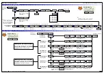
Setpoint Setup Sequence
0 No
Latching
1 Relay
Latched
2 Manual Relay Reset
3 Relay Latched and Manual Relay
Reset
4 Relay Latched Off
5 Hysteresis, Deviation & PID Mode
(includes SP Tracking)
6 Timer
Modes:
• OFF.
• Normal Delay.
• Repeat ON.
• Pulse ON.
• 1-Shot ON.
• Repeat OFF.
• Pulse OFF.
• 1-Shot OFF.
Note:
In PID Mode, all Timer Modes on
SP1 set in [XX6} are not functional.
7 Advanced Functions Mode:
• OFF.
• Reset Trigger.
• Reset Destination.
• Reset Mode.
• Reset Constant.
• Trigger Print from SP.
• Trigger Log from SP.
Note:
[XX5], [XX6], and [XX7] are set up
procedures only. To finish, reset to
0-4 as required for setpoint latching
and relay reset modes.
SETPOINT PROGRAMMING MODE – SPC_1 to SPC_6
Relay Energize Function
SP Activation Source
0
Activate Setpoint Source from
Selected Register
1 Select Source for Setpoint
Note:
[X1X] is a register selection procedure
only. To finish, reset to [X0X] to activate
the selection, or reset to 2-7 as required
for digital input selection.
2 Digital
Input
– Capture Pin
3 Digital
Input
– D1 (selected input modules)
4 Digital
Input
– D2 (selected input modules)
5 Digital
Input
– D3 (selected input modules)
6 HOLD Pin
7 LOCK Pin
*Note:
If the setpoint source is set to [oFF] or a
digital input, the setpoint activation value
will have no effect and will not be dis-
played.
SP Functions
FIRST DIGIT
SECOND DIGIT
THIRD DIGIT
SETPOINT AND RELAY CONTROL FUNCTION SETTINGS
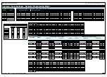
Select Source for Setpoint Functions
Go to
Page 12
Go to
Page 12
Go to
Page 13
[TOT_1]
[TOT_2]
[TARE]
[RESULT]
[CH1]
[CH2]
[CH3]
[CH4]
[DISP]
[ 1]
[ 2]
.....[ 10]
[ 11]
[ 12]
.....[ 20]
[ 100]
[ 200]
.....[ 239]
The
button takes you forward, the
button takes you back.
[AUX_5]
[VALLEY]
[PEAK]
[AUX_4]
[AUX_3]
[AUX_2]
[AUX_1]
Constant pressure on the
button moves thru Registers 1 to 239
one register at a time until you get to ten, then it jumps in multiples
of 10, until you reach 100, then it jumps in multiples of 100.
Stopping and starting again resumes single steps forward.
Use the
and
buttons to cycle through
the Registers Menu and
Registers (1 to 239) to
select the data source
for displays, peak and
valley, totalizers and
analog output.
0 Relay energizes ABOVE setpoint value
1 Relay energizes BELOW setpoint value
2 Relay energizes AT OR ABOVE setpoint value with FALLING INPUT
SIGNAL INITIAL START-UP INHIBIT
3 Relay energizes BELOW setpoint value with RISING INPUT SIGNAL
INITIAL START-UP INHIBIT
See Page 14 for a detailed description of the relay energize options.


