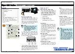


Tiger 320 Series Programming Code Sheet
Draft Copy. Code Version V3.08a
Texmate Inc. Tel. (760) 598 9899 • www.texmate.com
6
2 February, 2005 Prog. Code Sheet V3.08a (NZ101)
FRONT PANEL ANNUNCIATORS
0 ON when Setpoints are ON (relay
energized)
1 ON when Setpoints are OFF (relay
de-energized)
2 Always OFF.
See Note 1
3 LED SP1 ON indicates RISING sig-
nal trend.
LED SP2 ON indicates FALLING
signal trend.
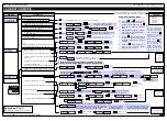
DISPLAY FUNCTIONS
0 Normal Display Mode (i.e. operational display
shows selected register)(updates every 0.5
seconds)
1 Manual Loader Mode (Direct display).
See Note*
2 Update at controlled output rate selected in Code 2
3 -
4 -
5 Select data source as per 3rd digit.
See Note 4
6 Select display format as per 3rd digit.
See Note 4
7 Select text character as per 3rd digit.
See Note 4
SELECT DATA SOURCE FOR
0 Primary Display
1 Second Display.
See Note 2
2 Third Display.
See Note 2
3 Peak/Valley
4 Analog Output 1
5 Analog Output 2
6 Totalizer 1
7 Totalizer 2
CODE 1 – DISPLAY CONFIGURATION
LAST DIGIT ROUNDING
0 No rounding
1 Rounding by 2’s
2 Rounding by 5’s
3 Rounding by 10’s
DISPLAY UNITS
0 Decimal
1 24-hour clock mode
Hours: Minutes:Seconds (6-digit version only)
2 12-hour clock mode (12:30 am is displayed as
12:30A. 12:30 pm is displayed as 12:30P)
3 24-hour clock mode
Days: Hours:Minutes (6-digit version only)
4 -
5 -
6 -
7 Octal
DECIMAL POINT PLACEMENT
0 No decimal point
1 XX.XX.XX (6 or 8-digit version only)
2
X.XXXXX (6 or 8-digit version only)
3
X.XXXX
4
X.XXX
5
X.XX
6
X.X
7 Decimal Point set from the rear
(X.XXXXX to XXXXXX).
See Note 3
.
Also See Note 4
DISPLAY FORMAT MODE
CODE 1
0 Result
1 Channel 1
2 Channel 2
3 Channel 3
4 Channel 4
5 Default Display
6 Total 1
7 Total 2
0 Result
1 Channel 1
2 Channel 2
3 Channel 3
4 Channel 4
5 Default Display
6 Total 1
7 Total 2
SELECT DISPLAY FORMAT FOR
SELECT TEXT CHARACTER FOR
FIRST DIGIT
SECOND DIGIT
THIRD DIGIT
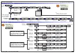
Note 1:
LED annunciators are always off, except when the meter is in single channel
VOLTAGE or CURRENT mode and Code 3 = [X6X], or Code 7 = [X6X] in
which case the LEDs indicate which 32-point table has been selected from the
rear pins (SP1 = Table 1, SP2 = Table 2, SP3 = Table 3, SP4 = Table 4).
Note 2:
These options are only for use with meters that have more than one dis-
play. With bargraph meters the PRIMARY display is the digital display, and
the SECONDARY display is the bargraph display.
Note 3:
These functions are only available on selected input modules.
Note 4:
If Code 1's display modes have been entered (second digit set to 5, 6, or
7), the display will cycle between Code 1 and the display functions mode
each time the PROGRAM button is pressed. To leave the cycle, the Code
1 digits must be reset to any relevant function between [X00] to [X20]. This
takes you into Code 2.
Select Data Source
Select Last Digit Text Character
P
FIRST DIGIT
SECOND DIGIT
THIRD DIGIT
Program the three digits to the required display function mode
Note*:
For the Manual Loader Mode (Direct Display) to work, with Code 1 set to
[X54] the data source for the analog output (1 or 2) must be set to [diSP].
Operating range upper and lower limits can be set for the manual loader
mode.
The setpoint activation values for setpoint 5 becomes the upper limit and
setpoint 6 becomes the lower limit.
When either the direct display or on demand manual loader mode is pro-
grammed into the meter, the values for setpoint 5 and setpoint 6 are acti-
vated as upper and lower limits.
See Analog Output Supplement for further details.
Note 5:
If only 4 kB memory installed, functions 2 to 6 are not available in:
•
Code 3 second digit.
•
Code 4 third digit.
•
Code 7 second digit.
Note 6:
These functions are not available on all models and in some cases require
additional hardware.
Note 7:
Only available with selected input modules.
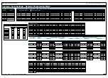
Note:
Selecting 1, 2, or 3 in the 2nd
digit of this mode configures
the display of the selected
channel as a clock.
Use the
button to cycle through the
menu, and the
button to cycle back.
[TOT_1]
[TOT_2]
[TARE]
[RESULT]
[CH1]
[CH2]
[CH3]
[CH4]
[DISP]
[ 1]
[ 2]
.....[ 10]
[ 11]
[ 12]
.....[ 20]
[ 100]
[ 200]
.....[ 239]
The
button takes you forward, the
button takes you back.
[AUX_5]
[VALLEY]
[PEAK]
[AUX_4]
[AUX_3]
[AUX_2]
[AUX_1]
Constant pressure on the
button moves thru Registers 1 to 239
one register at a time until you get to ten, then it jumps in multiples
of 10, until you reach 100, then it jumps in multiples of 100.
Stopping and starting again resumes single steps forward.
Use the
and
buttons to cycle through
the Registers Menu and
Registers (1 to 239) to
select the data source
for displays, peak and
valley, totalizers and
analog output.


