Texmate Tiger 320 Series Manual Download Page 13

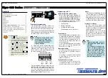
Tiger 320 Series Programming Code Sheet

Draft Copy. Code Version V3.08a

Texmate Inc. Tel. (760) 598 9899 • www.texmate.com

13

2 February, 2005   Prog. Code Sheet V3.08a (NZ101)
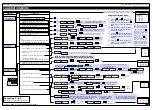
P

[diSP]

[rESLt]

[Ch1]

[Ch2]

[Ch3]

[Ch4]

[tot_1]

[tot_2]

[PEAK]

[VALEY]

[tArE]

[1 to 244]

P

P

P

Use the 
buttons  to cycle
through the menu

[brEAK]

[both]

[LEVEL]

Sets from 0 to –19999

[i-S+C]

[d+C]

[rEG]

Sets from 0 to 99999

Select Reset Destination Register

Select Reset Trigger

Select Reset Mode

Select Reset Constant

P

Select Print Triggered by Setpoint

P

Select Log Triggered by Setpoint

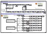
Advanced Functions Mode – Set Up Register Reset and Setpoint Trigger Functions

From Page 11,
3rd digit [XX7]

Selecting any destination
register takes you to
Mode Reset

Selecting [oFF] in the Destination
Register Reset Setup takes you
to Setpoint Print Trigger Setup

Select [rEG] to access the source parameter
to select the number of the Modbus register in
the meter to be copied to the reset destination
register 

X

X

P

X

X

Reset SPC to XX0

X

X

Use the 
buttons to cycle
through the menu

Programming Tip

If you do not require any
of the functions in this
mode, ensure it is set to:

Use the 

buttons

to select a register as the
data source for the set-
point (1 to 244)

Programming Tip

This mode can not be accessed if
SPC_1 or SPC_2 is in the PID mode.

Select reset 
trigger from
1 of 4 relay
operating
edges

Reset Trigger

Select register to be reset

Reset Destination Register

Select [Reg] in
reset mode

Reset Mode

Copy contents
of selected
register

SP1

to

SP6

Contents of

register copied into

reset destination

register  

Reset Destination Mode

The reset destination mode allows you to select a reg-
ister to be reset using the contents of another register
triggered by a setpoint. See diagram below.

Reset Trigger

Select the reset trigger from 1 of 4 relay operating
modes.

Reset Destination Register

Select the register to be reset from the commonly
used register set 1 to 244.

Reset Mode

1.

Select [rEG].

2.

Contents of selected register copied into reset
destination register.
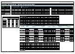
[TOT_1]

[TOT_2]

[TARE]

[RESULT]

[CH1]

[CH2]

[CH3]

[CH4]

[DISP]

[  1]

[  2]

.....[ 10]

[ 11]

[ 12]

.....[ 20]

[  100]

[  200]

.....[ 239]

The

button takes you forward,

the

button takes you back.

[AUX_5]

[VALLEY]

[PEAK]

[AUX_4]

[AUX_3]

[AUX_2]

[AUX_1]

Constant pressure on the

button moves thru

Registers 1 to 239 one register at a time until
you get to ten, then it jumps in multiples of 10,
until you reach 100, then it jumps in multiples of
100.

Stopping and starting again resumes single
steps forward.

Use the

and

buttons to cycle through
the Registers Menu and
Registers (1 to 239) to
select the data source
for displays, peak and
valley, totalizers and
analog output.

Summary of Contents for Tiger 320 Series

Page 1: ...on to all application function settings the configuration program also provides access to added features such as Code blanking Display text editing Configuration data copying Downloading macros to the...

Page 2: ...tware Version Number Press and hold the and buttons While holding both buttons press the Prog button then release all three buttons Programming Tip The Model and Software Code Version check ing proced...

Page 3: ...ideal for preventing settings such as calibra tion being changed by the operator Macros A macro is a set of commands that run auto matically when the controller is powered up Macros can be installed...

Page 4: ...s 8 9 and 10 shows the three digit configuration settings that are applied individually to each setpoint Display Brightness bri Allows you to adjust the display brightness in a range of 8 settings 0 b...

Page 5: ...time delay in milliseconds Except ASCII Mode which uses message terminators Use buttons to set AZ_A from 0 to 65535 counts P Auto zero motion Auto zero aperture window 0 1 Analog Output 1 2 Analog Out...

Page 6: ...options are only for use with meters that have more than one dis play With bargraph meters the PRIMARY display is the digital display and the SECONDARY display is the bargraph display Note 3 These fun...

Page 7: ...Register 2 2 Output Register 3 3 Output Register 4 4 Output Register 5 5 Output Register 6 6 Output Register 7 7 Smart Input Module Register 1 Code Setup See Note 7 THIRD DIGIT SECOND DIGIT CODE 2 No...

Page 8: ...ncy 99 999 Hz range from 0 001 Hz 1 Frequency 999 99 Hz range from 0 01 Hz 2 Frequency 99 999 kHz range from 1 Hz 1 s gate 3 Frequency 500 kHz range from 10 Hz 0 1 s gate 4 Period 9 9999 s 100 s resol...

Page 9: ...No Data Logging 1 Cyclic Buffer 2 Linear FIFO Buffer 3 Reset Buffer Number to 0 Note Setting Code 8 to 3XX resets the data log buffer to 0 Once reset Code 8 must be set back to the required data log...

Page 10: ...nts light up from the bottom of the bar and grow towards the top If bar nominal is set to the bar high setting this makes all seg ments from the displayed signal to the top of the bar light up As the...

Page 11: ...lay Latched and Manual Relay Reset 4 Relay Latched Off 5 Hysteresis Deviation PID Mode includes SP Tracking 6 Timer Modes OFF Normal Delay Repeat ON Pulse ON 1 Shot ON Repeat OFF Pulse OFF 1 Shot OFF...

Page 12: ...6553 5 65 535 secs DOB 0 1 0 001 to 6553 5 65 535 secs On_t 0 1 0 001 to 6553 5 65 535 secs Off time oFF_t 0 1 0 001 to 6553 5 65 535 secs Off time oFF_t 0 1 0 001 to 6553 5 65 535 secs Minimum off t...

Page 13: ...ramming Tip This mode can not be accessed if SPC_1 or SPC_2 is in the PID mode Select reset trigger from 1 of 4 relay operating edges Reset Trigger Select register to be reset Reset Destination Regist...

Page 14: ...illed Cases Totalizer 1 Flow Channel 2 Bottles SP5 2 00 Hi Setpoint SP6 2 00 Hi Setpoint SP4 12 Hi Setpoint SP3 12 Hi Setpoint S O U R C E R E S E T R E S E T I N C R E M E N T I N C R E M E N T S O U...

Page 15: ...022 SPAN 032 ZERO SPAN 042 CHANNEL 052 CHANNEL 012 INPUT INPUT INPUT CH2 023 SPAN 033 ZERO SPAN 043 CHANNEL 053 CHANNEL 013 INPUT INPUT INPUT CH3 024 SPAN 034 ZERO SPAN 044 CHANNEL 054 CHANNEL 014 IN...

Page 16: ...Y Serial Output Auto Zero Maintenance 210 AZ CAPTURE AZ MOTION AZ APERTURE 211 AZ CAPTURE AZ MOTION AZ APERTURE 212 AZ CAPTURE AZ MOTION AZ APERTURE 213 AZ CAPTURE AZ MOTION AZ APERTURE 214 AZ CAPTURE...

Page 17: ...CODE 2 PRESCALER 1st DIGIT 2nd DIGIT 3rd DIGIT CODE 3 1st DIGIT 2nd DIGIT 3rd DIGIT CODE 4 PRESCALER 1st DIGIT 2nd DIGIT 3rd DIGIT CODE 5 SMART INPUT MODULE SETTINGS 1st DIGIT 2nd DIGIT 3rd DIGIT COD...

Page 18: ...INT DER ARW MCT SP TRACKING SPAN PB INT DER ARW MCT SP TRACKING SPAN PB INT DER ARW MCT SP TRACKING SPAN PB INT DER ARW MCT SP TRACKING TIMER MODE SETTINGS SPC_1 _ _ 6 SPC_2 SPC_3 SPC_4 SPC_5 SPC_6 _...

Page 19: ...reset destination for the above func tions are shown in the table opposite This table shows in seven columns the functions where these registers can be used Where a register is more likely to be used...

Page 20: ...tion Select K Type Thermocouple for Initial Calibration S S T T E E P P 2 2 Enter the Calibration mode CAL set to 121 and press the button twice to carry out the thermocouple initial calibration proce...

Reviews: