


Tiger 320 Series Programming Code Sheet
Draft Copy. Code Version V3.08a
Texmate Inc. Tel. (760) 598 9899 • www.texmate.com
4
2 February, 2005 Prog. Code Sheet V3.08a (NZ101)
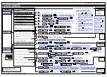
Tiger 320 Series Code Logic Diagram
To enter press the
and
buttons at the same time
P
Calibration Modes for Input and Output
Code 1 – Display Configuration
Code 2 – CH1 Measurement Task & Sampling Rate
Code 3 – CH1 Post Processing & Serial Mode Functions
Code 4 – CH2 Measurement Task & 32-point Linearization
Code 5 – CH3 Functions
Code 6 – CH4 Functions
Code 7 – Result Processing
Code 8 – Data Logging & Print Mode
Code 9 – Functions for Digital Input Pins
[CAL]
[Cod_1]
[Cod_2]
[Cod_3]
[Cod_4]
[Cod_5]
[
Cod_6]
[Cod_7]
[Cod_8]
[Cod_9]
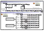
To enter press the
and
buttons at the same time
P
Setpoint 1
[SP_1]
Setpoint Activation Values Mode
Setpoint 2
[SP_2]
Setpoint 3
[SP_3]
Setpoint 4
[SP_4]
Setpoint 5
[SP_5]
Setpoint 6
[SP_6]
Enter these menus to set setpoint
(SP) activation values
Setpoint 1
[SPC_1]
Setpoint & Relay Control Settings Mode
Setpoint 2
[SPC_2]
Setpoint 3
[SPC_3]
Setpoint 4
[SPC_4]
Setpoint 5
[SPC_5]
Setpoint 6
[SPC_6]
Enter these menus to configure SP control
settings
See Page 5 for code settings to calibrate the meter’s input and output signals.
See Page 6 for code settings to configure the setpoint annunciators and other
display functions.
See Page 7 for code settings to configure the CH1 measurement task and sam-
pling rate.
See Page 8 for code settings to configure CH1 post processing and serial
mode functions.
See Page 8 for code settings to configure the second channel (CH2) meas-
urement task and 32-point linearization settings when using dual input signal
conditioners.
See Page 8 for code settings to configure the third channel (CH3) when using
triple input signal conditioners.
See Page 9 for code settings to configure the fourth channel (CH4) when
using quad input signal conditioners.
See Page 9 for code settings to configure the meter for processing the result
of CH1 and CH2.
See Page 9 for code settings to configure data logging and data printing
using the meter.
See Page 9 for code settings to configure the meter for inputs from external
sources through the digital input pins.
The
Setpoint and
Relay Control
Settings
diagram
on Pages 8, 9, and
10 shows the three
digit configuration
settings that are
applied individually
to each setpoint.
Display Brightness
[bri]
Allows you to adjust the display brightness in a range of 8 settings. 0 being
dull, 7 being bright.
Code 10 – Bargraph Setup
[Cod10]
See Page 10 for code settings to configure the meter’s bargraph display.
Main Programming Mode
Setpoint Programming Mode
P
P
P
P
P
P
P
P
P
P
P
P
P
P
P
P
P
P
P
P
P
P
P
Prog.
SP1
SP2
SP4
SP3
SP5
SP6
Operational Display
Prog.
SP1
SP2
SP4
SP3
SP5
SP6
Operational Display
P
Default setting = 18000
Default setting = –18000
Default setting = 5000
Default setting = –5000
Default setting = 10000
Default setting = –10000
Prog.
SP1
SP2
SP4
SP3
SP5
SP6
Operational Display
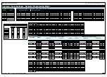
Tiger 320 Series Programmable Meter Controllers (PMCs) come in
two versions: the economy E version, or the top-of-the-line T version.
The standard E version comes with 4 kilobits of EEPROM installed,
whereas the standard T version comes with 32 kilobits of EEPROM
Installed. Also, the T version can have a macro installed.
The standard 4-kilobit E version can be upgraded to 32 or 512 kilobits.
The standard 32-kilobit T version can be upgraded to 512 kilobits. The
amount of EEPROM installed in the controller determines the range of
functions it is capable of performing. The following table lists the func-
tions that require specific amounts of memory.
Version
Functions
Memory
(kilobits)
Remarks
E
1 linearization table
4 (standard)
Table 1 is available to
be applied to chan-
nels 1 to 4 and result.
4 linearization tables
32
Tables 1 to 4 are
available to be
applied to channels 1
and 2 and result.
Table 3 can be applied
to channel 3.
Table 4 can be applied
to channel 4.
All four tables can be
cascaded to form a
single 125-point lin-
earization table avail-
able to be applied to
channels 1 and 2 and
result.
Data logging
512
With 512 kilobits
installed, the controller
can perform data log-
ging functions along
with complete lin-
earization functionali-
ty. With a real-time
clock installed, date
and time stamps can
be included.
T
4 linearization tables
32 (standard)
As for E version with
32 kilobits installed.
Macro programming
A macro can be pro-
grammed to suit a
user's logic control
application.
Data logging
512
As for E version with
512 kilobits installed,
but with macro pro-
gramming functionali-
ty available.
E/T Versions of Tiger 320 Series Programmable Meter Controller


