


Tiger 320 Series Programming Code Sheet
Draft Copy. Code Version V3.08a
Texmate Inc. Tel. (760) 598 9899 • www.texmate.com
20
2 February, 2005 Prog. Code Sheet V3.08a (NZ101)
User Notes
WARRANTY
Texmate warrants that its products are free from defects in material and workmanship under
normal use and service for a period of one year from date of shipment. Texmate’s obligations
under this warranty are limited to replacement or repair, at its option, at its factory, of any of
the products which shall, within the applicable period after shipment, be returned to Texmate’s
facility, transportation charges pre-paid, and which are, after examination, disclosed to the sat-
isfaction of Texmate to be thus defective. The warranty shall not apply to any equipment which
shall have been repaired or altered, except by Texmate, or which shall have been subjected to
misuse, negligence, or accident. In no case shall Texmate’s liability exceed the original pur-
chase price. The aforementioned provisions do not extend the original warranty period of any
product which has been either repaired or replaced by Texmate.
USER’S RESPONSIBILITY
We are pleased to offer suggestions on the use of our various products either by way of print-
ed matter or through direct contact with our sales/application engineering staff. However, since
we have no control over the use of our products once they are shipped, NO WARRANTY
WHETHER OF MERCHANTABILITY, FITNESS FOR PURPOSE, OR OTHERWISE is made
beyond the repair, replacement, or refund of purchase price at the sole discretion of Texmate.
Users shall determine the suitability of the product for the intended application before using,
and the users assume all risk and liability whatsoever in connection therewith, regardless of
any of our suggestions or statements as to application or construction. In no event shall
Texmate’s liability, in law or otherwise, be in excess of the purchase price of the product.
Texmate cannot assume responsibility for any circuitry described. No circuit patent or software
licenses are implied. Texmate reserves the right to change circuitry, operating software, spec-
ifications, and prices without notice at any time.
For product details visit www.texmate.com
Local Distributor Address
995 Park Center Drive • Vista, CA 92081-8397
Tel: 1-760-598-9899 • USA 1-800-839-6283 • That’s 1-800-TEXMATE
Fax: 1-760-598-9828 • Email: [email protected] • Web: www.texmate.com
Texmate has facilities in Japan, New Zealand, Taiwan, and Thailand. We also have
authorized distributors throughout the USA and in 28 other countries.
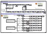
Converting °F to °C
1) Calibrate the meter to suit the temperature sensor input.
Use K type thermocouple input for thermocouples.
Use RTD 385 for RTDs.
2) To convert °F to °C enter the calibration mode and set [CAL] to [10X].
3) Set the offset [OFFS_R] to [–178] counts on the display.
4) Set the scale factor [SCAL_R] to [0.55555] on the display.
Ignore the decimal point on OFFSET settings
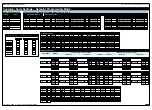
Thermocouple Calibration for CH1
S
S T
T E
E P
P 1
1
Enter Code 2 and select K type
thermocouple for initial calibration.
Select K Type Thermocouple for Initial Calibration
S
S T
T E
E P
P 2
2
Enter the Calibration mode [CAL], set
to [121] and press the
button twice
to carry out the thermocouple initial
calibration procedure.
Thermocouple Initial Calibration
S
S T
T E
E P
P 4
4
Select Thermocouple Type
Re-enter Code 2 and select the
required thermocouple type, noise
rejection setting, and the analog
sampling and output rate.
Select thermocouple type:
Select noise rejection, analog sampling & output rate:
S
S T
T E
E P
P 5
5
Enter the Calibration mode [CAL], set to
[111] and fine tune the thermocouple
calibration over the required temperature
range.
Fine Tune Calibration over Specific Temperature Range
Follow Steps 1 to 4 for setting channels 2 and 3, using the following settings:
CH2
:
Code 4 [11X] for K type, CAL [122] to calibrate K type, Code 4 [1X0]
to select specific TC, CAL [112] to trim selected TC.
CH3
:
Code 5 [X21] for K type, CAL [123] to calibrate K type, Code 5 [X2X]
to select specific TC, CAL [113] to trim selected TC.
For a detailed thermocouple calibration procedure, see Advanced Calibration & On
Demand Mode Supplement (NZ203).
S
S T
T E
E P
P 3
3
Select Temperature Units
Enter the Calibration mode [CAL], set
to [101].
If you want °F set offset to 0 and scale
factor to 1.
If you want °C set offset to 0.5555 and
scale factor to –178.
Note, once the temperature units have been select-
ed, the temperature inputs to the meter must be in
the same units.
Note, this is not a
mandatory step.
Carry out only if
required.
See Converting °F to °C
procedure opposite.
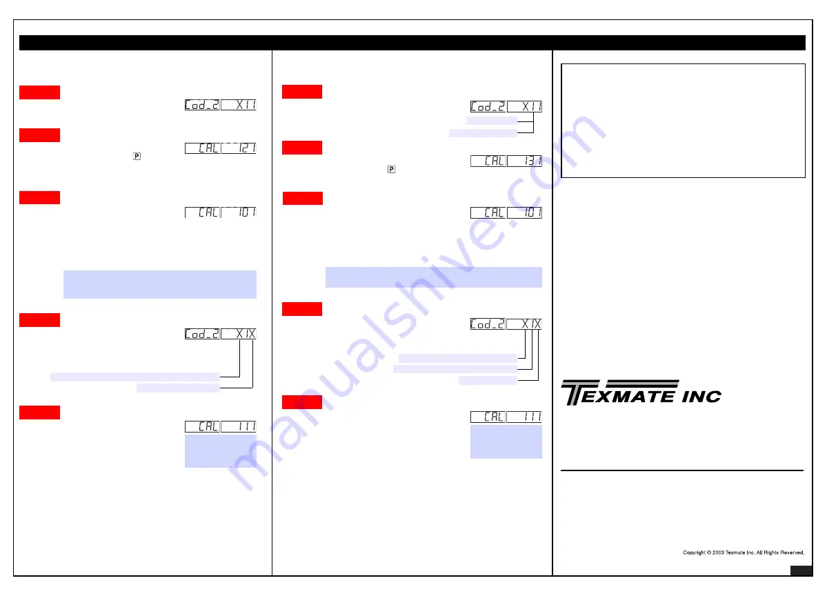
CH1 Initial RTD Calibration
S
S T
T E
E P
P 1
1
Enter Code 2 and select type Pt 385
100
Ω
RTD for initial calibration.
Select Type Pt 385 100
Ω
RTD
S
S T
T E
E P
P 2
2
Enter the Calibration mode [CAL], set to
[131] and press the
button once to carry
out the RTD initial calibration procedure.
RTD Initial Calibration
S
S T
T E
E P
P 4
4
Select RTD Type
Re-enter Code 2 and select the
required RTD type, noise rejection
setting, and the analog sampling and
output rate.
S
S T
T E
E P
P 5
5
Enter the Calibration mode [CAL], set
to [111] and fine tune the RTD calibration
over the required temperature range.
Calibration Trim
Follow Steps 1 to 4 for setting channels 2 and 3, using the following settings:
CH2
:
Code 4 [210] for type 385, CAL [132] to calibrate type 385, Code 4
[2X0] to select specific RTD, CAL [112] to fine tune selected RTD.
CH3
:
Code 5 [X31] for type 385, CAL [133] to calibrate type 385, Code 5
[X3X] to select specific RTD, CAL [113] to fine tune selected RTD.
CH4
:
Code 6 [X31] for type 385, CAL [134] to calibrate type 385, Code 6
[X3X] to select specific RTD, CAL [113] to fine tune selected RTD.
For a detailed RTD calibration procedure, see Advanced Calibration & On Demand
Mode Supplement (NZ203).
3
= RTD 2 or 4-wire
2
= RTD 3-wire
Select RTD type:
Select analog sampling & output rate:
2
= RTD 3-wire,
3
= RTD 2 or 4-wire:
S
S T
T E
E P
P 3
3
Select Temperature Units
Enter the Calibration mode [CAL], set to [101].
If you want °F set offset to 0.0 and scale fac-
tor to 1.0000.
If you want °C set offset to 0.5555 and scale
factor to –178.
Note, once the temperature units have been selected, the
temperature inputs to the meter must be in the same units.
See Converting °F to °C
procedure opposite.
Note, this is not a
mandatory step.
Carry out only if
required.


