


Tiger 320 Series Programming Code Sheet
Draft Copy. Code Version V3.08a
Texmate Inc. Tel. (760) 598 9899 • www.texmate.com
2
2 February, 2005 Prog. Code Sheet V3.08a (NZ101)
SP1
SP2
SP3
SP4
SP5
SP6
Prog.
SP1
SP2
SP3
SP4
SP5
SP6
Prog.
SP1
SP2
SP3
SP4
SP5
SP6
Prog.
SP1
SP2
SP3
SP4
SP5
SP6
Prog.
SP1
SP2
SP3
SP4
SP5
SP6
Prog.
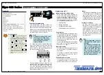
MODEL &
SOFTWARE
CODE VERSION
CHECK
Press
then
once
release
Press
and
hold
Step 1
Step 2
Step 3
The above displays toggles
three times before returning to
the operational display
SP1
SP2
SP3
SP4
SP5
SP6
Prog.
Operational Display
Operational Display
Example
Release
after
pressing
Prog.
Model
Number
Typical
Software
Version
Number
Press and hold
the and
buttons
While holding both
buttons, press the Prog.
button then release
all three buttons
Programming Tip
The
Model and Software Code Version
check-
ing procedure can be performed at any time
without interfering with other configuration
settings.
ST
ST
AR
AR
T HERE
T HERE
a
b
c
Model No:
............................................................................
Software Version No:
..................................................
Customer ID:
......................................................................
Macro ID:
..............................................................................
Initial Setup Procedures
Model and Software Code Version Check
The meter model and software code version number can be
checked at any time while in the operational display using the
following procedure.
Before configuring the meter, carry out the following meter
configuration checks:
• Model and software code version check.
• Code blanking and macro check.
After powering-up the meter, check the model and software
code version number and note this below.


