

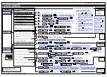


Tiger 320 Series Programming Code Sheet
Draft Copy. Code Version V3.08a
Texmate Inc. Tel. (760) 598 9899 • www.texmate.com
17
2 February, 2005 Prog. Code Sheet V3.08a (NZ101)
1st DIGIT
2nd DIGIT
3rd DIGIT
CODE 1
X52
X53
X54
X55
X56
X57
X60
DISPLAY
X63
X65
X66
X67
X64
X50
X51
X62
X61
SOURCE
SOURCE
SOURCE
SOURCE
SOURCE
SOURCE
SOURCE
SOURCE
DISPLAY
DISPLAY
DISPLAY
DISPLAY
DISPLAY
DISPLAY
DISPLAY
X72
X73
X74
X75
X76
X77
X70
X71
CHARACTER
CHARACTER
CHARACTER
CHARACTER
CHARACTER
CHARACTER
CHARACTER
CHARACTER
1st DIGIT
2nd DIGIT
3rd DIGIT
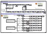
CODE 2
PRESCALER
1st DIGIT
2nd DIGIT
3rd DIGIT
CODE 3
1st DIGIT
2nd DIGIT
3rd DIGIT
CODE 4
PRESCALER
1st DIGIT
2nd DIGIT
3rd DIGIT
CODE 5
SMART INPUT MODULE
SETTINGS
1st DIGIT
2nd DIGIT
3rd DIGIT
CODE 6
SMART INPUT MODULE
SETTINGS
1st DIGIT
2nd DIGIT
3rd DIGIT
CODE 7
1st DIGIT
2nd DIGIT
3rd DIGIT
CODE 8
1st DIGIT
2nd DIGIT
3rd DIGIT
CODE 9
SUB-SETTINGS
1st DIGIT
2nd DIGIT
3rd DIGIT
CODE 10
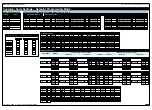
2XX COLOR 1
BARGRAPH COLORS
COLOR 2
COLOR 3
COLOR 4
COLOR 5
COLOR 6
COLOR 7
SCALING FOR LINEAR BARGRAPH
3X0
BAR LOW
BAR HIGH
BAR NOMINAL
3X1
BAR LOW
BAR HIGH
BAR NOMINAL
SCALING FOR LOGIRITHMIC BARGRAPH
3X3
REFERENCE
BAR NOMINAL
3X4
REFERENCE
BAR NOMINAL
3X5
REFERENCE
BAR NOMINAL
3X6
REFERENCE
BAR NOMINAL
3X7
REFERENCE
BAR NOMINAL


