


CC112X/CC1175
SWRU295C
Page 36 of 108
T1:
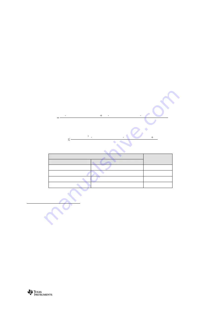
The time the AGC waits after adjusting the front end gain to allow signal transients to decay
before the next signal strength measurement can take place. T1 can be calculated using Equation 13.
T2:
The time the AGC uses to measure the signal strength and potentially adjust the gain. T2 can be
calculated using Equation 14.
The CS response time is the time it takes before
maximum
time the radio will be in RX state when RX termination based on CS is enabled (see
Section 8.5.2 for more details). The CS response time is given by
Figure 14 shows an example of how RSSI computation speed/update rate can be traded against
RSSI accuracy. In the case where
AGC_CFG0.RSSI_VALID_CNT = 00b
the number of new input
samples to the moving average filter is 2, making the CS response time short but might lead to a less
robust CS indication on the second RSSI update. In the case where
= 10b
(5 samples) there are no failing CS, but the response time is longer.
is found in register
register fields are found in the
register.
is found in
. The decimation factor is 20 or 32, given by the
XOSC
f
Factor
Decimation
FACT
BB_CIC_DEC
)
48
_WAIT
AGC_SETTLE
16
(
T1
Equation 13: T1
XOSC
f
46
Factor
Decimation
FACT
BB_CIC_DEC
2
T2
4
ZE
AGC_WIN_SI
Equation 14: T2
Configuration Register Fields/Conditions
T0
CHAN_BW.CHFILT_BYPASS
CHAN_BW.BB_CIC_DECFACT > 0x01
0
0
D
0
+ D
2
+ D
4
0
1
D
0
+ D
1
+ D
3
+ D
5
1
0
D
0
1
1
D
0
+ D
1
+ D
6
Table 20: T0 Matrix
9