3-50
Z
®
-33/18
Part No. 1268514GT
January 2020
Section 3 • Repair Procedures
Motor Controller
There are two drive motor controllers located
inside the non-steer axle, one for each drive
motor. When viewed from the non-steer end of
the machine, the right side motor controller is the
"master" and the left side motor controller is the
"slave." The master motor controller controls the
right drive motor and the function pump. The slave
motor controller controls the left side drive motor
and auxiliary power unit. The motor controllers
are also AC voltage inverters which take the DC
voltage from the system batteries and convert the
voltage to AC power for the drive motors.
The motor controllers are in communication with
the turntable controller (TCON) and the platform
controller (PCON) which are able to communicate
operating or fault information to the LCD display at
the platform controls.
The motor controllers also control the valve
outputs and machine options such as flashing
beacon, travel alarm, etc.
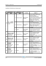
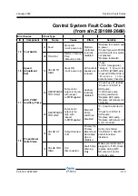
Refer to Section 5,
Fault Codes
for a list of fault
codes and additional information.
For further information or assistance, consult the
Genie Industries Service Department.
*NODE 5*
Outputs/
AUX Pump
*NODE 4*
Left Drive Motor
*NODE 2*
Outputs/Lift Pump
(Net Master)
*NODE 3*
Right Drive Motor
TCON
System Controller
(Master)
PCON
Drive / Steer
Inputs
Right (Master)
Motor Controller
Left (Slave)
Motor Controller
VCON
Visual Controller
(LCD Display)
Summary of Contents for Genie Z-33/18
Page 6: ...vi Z 33 18 Part No 1268514GT January 2020 This page intentionally left blank ...
Page 12: ...xii Z 33 18 Part No 1268514GT January 2020 This page intentionally left blank ...
Page 104: ...5 2 Z 33 18 Part No 1268514GT January 2020 Section 5 Schematics Electrical Symbols Legends ...
Page 105: ...January 2020 Part No 1268514GT Z 33 18 5 3 Section 5 Schematics Hydraulic Symbols Legends ...
Page 106: ...January 2020 Section 5 Schematics 5 4 5 5 Electrical Schematic ...
Page 108: ...January 2020 Section 5 Schematics 5 7 Electrical Schematic ...
Page 110: ...January 2020 Section 5 Schematics 5 9 Electrical Schematic ...
Page 112: ...January 2020 Section 5 Schematics 5 11 Electrical Schematic ...
Page 114: ...January 2020 Section 5 Schematics 5 13 Electrical Schematic ...
Page 117: ...5 16 Z 33 18 Part No 1268514GT January 2020 Section 5 Schematics Hydraulic Schematic ...


