January 2020
Part No. 1268514GT
Z
®
-33/18
3-37
Section 3 • Repair Procedures
MANIFOLDS
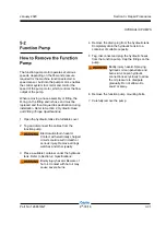
Note: Perform this procedure with the machine in
the stowed position.
1 Connect a 0 to 3000 PSI / 0 to 207 bar
pressure gauge to test port TP1 on the function
manifold.
2 Turn the key switch to Ground control. Pull out
the platform red Emergency Stop button to the
on position and pull out the ground control red
Emergency stop button to the on position.
3 To enter the pressure sensor calibration mode
(after startup beep) triple click the ground
control function enable button within 5 seconds
of pulling the red Emergency Stop button at the
ground controls.
The pump motor activates and a green light will
begin flashing on the TCON controller.
Note: The procedure will time out if any step is not
completed within 90 seconds or terminate if the
function enable switch is activated.
4 Simultaneously activate the platform level
toggle switch until the pressure gauge reads
1000 PSI / 69 bar. The platform level toggle
up increases pressure, platform level down
decreases pressure.
5 Simultaneously activate the platform rotate
toggle switch to store the value.
Result: The control system will continue to the
next calibration procedure value - (3000 PSI /
207 bar).
6 Simultaneously activate the platform level
toggle switch until the pressure gauge reads
3000 PSI / 207 bar. The platform level toggle
up increases pressure, platform level down
decreases pressure.
7 Simultaneously activate the platform rotate
toggle switch to save the value.
Result: The control system will automatically
continue to the next procedure, calibrate and
save for the remaining values: 2500 PSI / 172
bar, 2000 PSI / 138 bar. A one second pulse
alarm will indicate the calibration procedure is
complete.
8 Remove the pressure gauge.
Summary of Contents for Genie Z-33/18
Page 6: ...vi Z 33 18 Part No 1268514GT January 2020 This page intentionally left blank ...
Page 12: ...xii Z 33 18 Part No 1268514GT January 2020 This page intentionally left blank ...
Page 104: ...5 2 Z 33 18 Part No 1268514GT January 2020 Section 5 Schematics Electrical Symbols Legends ...
Page 105: ...January 2020 Part No 1268514GT Z 33 18 5 3 Section 5 Schematics Hydraulic Symbols Legends ...
Page 106: ...January 2020 Section 5 Schematics 5 4 5 5 Electrical Schematic ...
Page 108: ...January 2020 Section 5 Schematics 5 7 Electrical Schematic ...
Page 110: ...January 2020 Section 5 Schematics 5 9 Electrical Schematic ...
Page 112: ...January 2020 Section 5 Schematics 5 11 Electrical Schematic ...
Page 114: ...January 2020 Section 5 Schematics 5 13 Electrical Schematic ...
Page 117: ...5 16 Z 33 18 Part No 1268514GT January 2020 Section 5 Schematics Hydraulic Schematic ...


