


3-46
Z
®
-33/18
Part No. 1268514GT
January 2020
Section 3 • Repair Procedures
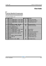
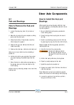
STEER AXLE COMPONENTS
8 Momentarily activate the steer rocker switch in
the right direction until you see the
CALIBRATE
CENTER
screen.
9 Momentarily activate the drive enable toggle
switch in the right direction to enter the
CALIBRATE CENTER
screen.
Result: The display will show
OUT OF RANGE
or
IN RANGE
according to the wheels position.
10 Momentarily activate the drive enable toggle
switch in the right direction to save the setting
(if steer sensor mV value is IN RANGE).
Result: The alarm should sound indicating the
setting has been saved.
11 Momentarily activate the steer rocker switch in
the right direction until you see the CALIBRATE
RIGHT screen.
12 Adjust the steer wheels fully in the right
direction.
13 Momentarily activate the drive enable toggle
switch in the right direction to enter the
CALIBRATE RIGHT
screen.
Result: The display will show
OUT OF RANGE
or
IN RANGE
according to the wheels position.
14 Momentarily activate the drive enable toggle
switch in the right direction to save the setting
(if steer sensor mV value is IN RANGE).
Result: The alarm should sound indicating the
setting has been saved.
15 Momentarily activate the steer rocker switch in
the right direction until you see the
CALIBRATE
LEFT
screen.
16 Adjust the steer wheels fully in the left direction.
17 Momentarily activate the drive enable toggle
switch in the right direction to enter the
CALIBRATE LEFT
screen.
Result: The display will show
OUT OF RANGE
or
IN RANGE
according to the wheels position.
Summary of Contents for Genie Z-33/18
Page 6: ...vi Z 33 18 Part No 1268514GT January 2020 This page intentionally left blank ...
Page 12: ...xii Z 33 18 Part No 1268514GT January 2020 This page intentionally left blank ...
Page 104: ...5 2 Z 33 18 Part No 1268514GT January 2020 Section 5 Schematics Electrical Symbols Legends ...
Page 105: ...January 2020 Part No 1268514GT Z 33 18 5 3 Section 5 Schematics Hydraulic Symbols Legends ...
Page 106: ...January 2020 Section 5 Schematics 5 4 5 5 Electrical Schematic ...
Page 108: ...January 2020 Section 5 Schematics 5 7 Electrical Schematic ...
Page 110: ...January 2020 Section 5 Schematics 5 9 Electrical Schematic ...
Page 112: ...January 2020 Section 5 Schematics 5 11 Electrical Schematic ...
Page 114: ...January 2020 Section 5 Schematics 5 13 Electrical Schematic ...
Page 117: ...5 16 Z 33 18 Part No 1268514GT January 2020 Section 5 Schematics Hydraulic Schematic ...