January 2020
Part No. 1268514GT
Z
®
-33/18
3-35
Section 3 • Repair Procedures
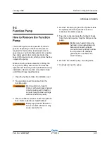
This procedure must be performed at the ground
controls.
1 Turn the key switch to the off position, and
push in the red Emergency Stop button to the
off position.
2 Connect a 0 to 3000 psi / 0 to 207 bar pressure
gauge to test port TP1 on the function manifold.
3 Turn the key switch to the ground control
position. Pull out the red Emergency Stop
button to the on position and immediately
activate the function enable toggle switch in
either direction 3 times after the alarm sounds.
The function enable toggle switch must be
activated within 2 seconds of the audible tone.
Result: The green LED on the TCON should
change from a slow blinking light to a rapid
blinking light.
Result: The green LED on the TCON does
not blink rapidly. Push in the red Emergency
Stop button to the off position and repeat this
procedure beginning with step 3.
a green LED
b red LED
c turntable control module (TCON)
4 Move and hold the primary boom toggle switch
in the extended direction.
The pressure gauge shows 1100 psi / 76 bar.
Continue to step 6.
The pressure gauge does not show 1100 psi /
76 bar. Continue to step 5.
Do not activate the function enable toggle switch
while making this adjustment.
b
a
c
MANIFOLDS
Summary of Contents for Genie Z-33/18
Page 6: ...vi Z 33 18 Part No 1268514GT January 2020 This page intentionally left blank ...
Page 12: ...xii Z 33 18 Part No 1268514GT January 2020 This page intentionally left blank ...
Page 104: ...5 2 Z 33 18 Part No 1268514GT January 2020 Section 5 Schematics Electrical Symbols Legends ...
Page 105: ...January 2020 Part No 1268514GT Z 33 18 5 3 Section 5 Schematics Hydraulic Symbols Legends ...
Page 106: ...January 2020 Section 5 Schematics 5 4 5 5 Electrical Schematic ...
Page 108: ...January 2020 Section 5 Schematics 5 7 Electrical Schematic ...
Page 110: ...January 2020 Section 5 Schematics 5 9 Electrical Schematic ...
Page 112: ...January 2020 Section 5 Schematics 5 11 Electrical Schematic ...
Page 114: ...January 2020 Section 5 Schematics 5 13 Electrical Schematic ...
Page 117: ...5 16 Z 33 18 Part No 1268514GT January 2020 Section 5 Schematics Hydraulic Schematic ...


